AGM (Attitude generator module)
AGM Overview
The Attitude Generation Module (AGM) is a software library developed to support implementing science operations planning systems with capabilities to schedule pointing, slew and maintenance blocks according to the Interface Control Documents (ICD) provided by Flight Dynamics (FDY) to the Science Operations Centres (SOC).
AGM Configuration File
This section documents certain relevant aspects of the AGM configuration file. All settings and values are case insensitive.
Note: When specifing Default value, we are meaning about the default AGM setting value if
not present in the AGM Configuration File, not the default value to be used by a specific mission setup.
Error Reporting Configuration
The error reporting configuration defines how the system handles and limits the reporting of messages based on severity and quantity. To configure error reporting, add the following settings to the configuration file:
ER_MAXNROFMESSAGES: Maximum number of messages to report. Default: 100ER_SEVERITYTHRESHOLD: Code for choosing the minimum severity level to report a given message. Default: debug
Spacecraft Characterisation
The spacecraft characterisation defines the physical properties of the S/C used in attitude and dynamics computations. To configure these parameters, add the following settings to the configuration file:
SC_INERTIA: S/C inertia tensor (unit:kg*m^2). Matrix format:xx, xy, xz, yx, yy, yz, zx, zy, zz
Reaction wheels characterisation
RW_SC2RW: S/C to RW orientation matrix (unit:-). Matrix format:1x, 1y, 1z, 2x, 2y, 2z, 3x, 3y, 3z, 4x, 4y, 4z
RW_SCANGMOMMAX: Maximum S/C angular momentum to be managed by the legacy reaction wheel model (unit:N*m*s).Not applicable to JUICE. Default: 0.0, means AGM Legacy RW Model is Disabled.
Slew Estimation Algorithm
The slew estimation algorithm defines how the system calculates and optimizes the slew duration and path during attitude transitions. To configure the slew estimation algorithm, add the following settings to the AGM configuration file:
SE_SLEWNROFSEG: Code for choosing the number of segments of the slew profile. Default:1segment. Available options:1SEGMENT: 1 Segment slew. (Acceleration + Deceleration)3SEGMENT: 3 Segment slew. (Acceleration + Constant Rate + Deceleration).
SE_SLEWPATH: Code for choosing the slew path. Default:sunLineMX. Available options:SUNLINEMX: Sun line MX to avoid the Sun on the +X.SUNLINEPX: Sun line PX to avoid the Sun on the -X.EIGENAXIS: Eigen axis to minimise angular inertia.SUNLINEXY_MY: Sun line XY MY.NORMAL TO X AVOID +YNORMAL TO X AVOID -YNORMAL TO X AVOID +ZNORMAL TO X AVOID -ZNORMAL TO Y AVOID +XNORMAL TO Y AVOID -XNORMAL TO Y AVOID +ZNORMAL TO Y AVOID -ZNORMAL TO Z AVOID +XNORMAL TO Z AVOID -XNORMAL TO Z AVOID +YNORMAL TO Z AVOID -YNADIR +XNADIR -XNADIR +YNADIR -YNADIR +ZNADIR -ZCONSTANT ROLLEIGENAXIS2
SE_SUNREFPERCENT: Reference time for Sun direction along the slew duration (in %). Default:0.0.SE_DURATIONMIN: Minimum slew duration allowed (in seconds). Default:10.0.SE_DURATIONMAX: Maximum slew duration allowed to shorten estimation (in seconds). Default:0.0.SE_ACCURACY: Accuracy for the slew duration estimation (in seconds). Default:1.0.SE_MARGINPERCENT: Margin to be applied on the estimated slew duration (in %). Default:10.0.SE_MARGINDELTA: Extra time to be added on the estimated slew duration (in seconds). Default:0.0DISABLED.SE_REPORT_SLEW_SOLUTION: Flag to indicate whether if slew solutions (before/after) should be reportedto the user in order to avoid attitude constraint breaks (for example, momentum, torque, etc.)… Default:
False.
SE_SLEW_SOLUTION_ACCURACY: Indicates the time accuracy in seconds at which the algorithmshould stop looking for a solution. 1 minute could be a reasonable time accuracy. The higher the accuracy the longer the time the algorithm will try to find a solution, and therefore, it has an impact in the performance. Default:
60.0.
SE_REPORT_COMPOSITE_SLEW_SOLUTION: Flag to indicate whether if composite blocks slew solutions should be reportedto the user in order to avoid attitude constraint breaks (for example, momentum, torque, etc.)… Default:
False.
SE_WMM_CHECKS_ENABLED: Flag to perform WMM checks during slew estimation. Default:False.
Attitude Generation Algorithms
The attitude generation algorithms define how the attitude profile is generated and optimized during science and composite pointing blocks. To configure these algorithms, add the following settings to the AGM configuration file:
AG_DURATIONMIN: Minimum block duration allowed (in seconds). Default:10.0.AG_PROFILETIMESTEP: Time step for the attitude profile generation (in seconds). Default:60.0.AG_SETTLINGTIMEBEFORE: Settling time at the start of a science pointing block (in seconds), only used for updating inSettling overlay flag. Default:0.0.AG_SETTLINGTIMEAFTER: Settling time at the end of a science pointing block (in seconds), only used for updating inSettling overlay flag. Default:0.0.AG_COMPSETTLINGTIMEBEFORE: Settling time at the start of each composite internal science pointing slot (in seconds), only used for updating inSettling overlay flag. Default:0.0.AG_COMPSETTLINGTIMEAFTER: Settling time at the end of each composite internal science pointing slot (in seconds), only used for updating inSettling overlay flag. Default:0.0.AG_GAPDURATIONMIN: Minimum gap duration in timeline to try filling with the default pointing (in seconds). Default:0.0Gap filling disabled.AG_FILLGAPSSTARTANDEND: Flag to fill gaps with default pointing block in both timeline start and end (True/False). Default:falseGap filling disabled.AG_MERGEBLOCKSWITHDEFAULTBLOCK: Flag to merge blocks with the default block (True/False). Default:false.AG_SOLARARRAYSDIR: SA rotation axis vector in the SC Frame (vector x,y,z), both vectors AC_SA_ROT_ZREF and AG_SOLARARRAYSDIR defines the SA Plane on rotation angle 0 degrees. Default:0, 1, 0.
Attitude Constraints Checks
The attitude constraint checks defines how the slew estimator is going to behave while resolving and assuring the viability of the simulated pointing timeline. In order to configure the attitude constraint checks just add the following settings to the AGM configuration file:
AC_POINTINGDURATIONMIN: Minimum duration of a pointing block (in seconds) (whatever is between block; in the PTR file).This includes the SLEWs and the Engineering activities like OCMs and WOLs. Default:
0.0
AC_SLEWDURATIONMIN: Minimum duration of a slew block in seconds. Default:0.0AC_GSEPSLEWDURATIONMIN: Minimum duration of a slew block before/after a ExoMars TGO GSEP block in seconds. Not applicable to JUICE. Default:0.0.AC_COMPOSITEDURATIONMIN: Minimum duration of each composite internal pointing slot in seconds. Default:0.0AC_COMPOSITETIMEBEFORE: Minimum time required in composite pointing blocks before the offset rotations in seconds. Default:0.0AC_COMPOSITETIMEAFTER: Minimum time required in composite pointing blocks after the offset rotations in seconds. Default:0.0AC_FLIPDURATION:NadirPowerOptimizeflip duration in seconds. Not applicable to JUICE. Default:0.0.AC_FLIPMARGIN: Margin from the beginning or the end of the pointing to place the ExoMars TGO NadirPowerOptimize flip. Not applicable to JUICE. Default:0.0.AC_FLIPACCELERATION: Acceleration indeg/s^2for ExoMars TGO Yaw angle during the acc/dec periods during a flip. Not applicable to JUICE. Default:0.0.AC_WOLDURATION: This is the standard ExoMars TGO wheel offloading maintenance block duration. The WOL duration cannot be below this value. Not applicable to JUICE Default: 0.0AC_CHECKTIMESTEP: Time step for the attitude constraints checking in seconds. Default:1.0AC_SCANGVELMAX: Maximum angular velocity allowed for the S/C in degrees/second. If set to 0 then this check is disabled. Default:0.0AC_SCANGVELMAXAXIS: Vector with the maximum angular velocities allowed for the S/C per axis in degrees/second. If any axis is set to 0 then this axis check is disabled. Default:0.0 0.0 0.0.AC_SCANGACCMAX: Maximum angular acceleration allowed for the S/C in degrees/second. If set to 0 then this check is disabled. Default:0.0AC_SCANGACCMAXAXIS: Vector with the maximum angular acceleration allowed for the S/C per axis in degrees/second. If any axis is set to 0 then this axis check is disabled. Default:0.0 0.0 0.0.
Attitude Constraints Check: Reaction Wheels and Wheel Momentum Management
In order to configure the reaction wheels just add the following settings to the AGM configuration file:
Note: All the vectors in this section have four elements.
AC_RWTORQUEMIN: Vector with the minimum torque allowed for each RW in N*m.This is a parameter for a Legacy Model not used in the simulation but present for backwards compatibility. These values are used in the slew duration calculation algorithm that is independent on past and future spacecraft state. NOTE: Just for legacy RW module, not used in the WMM. Not applicable to JUICE. Default:
0.0 0.0 0.0 0.0. All wheels check DISABLED.
AC_RWTORQUEMAX: Vector with the maximum torque allowed for each RW in N*m.This is a parameter for a Legacy Model not used in the simulation but present for backwards compatibility. These values are used in the slew duration calculation algorithm that is independent on past and future spacecraft state. NOTE: Just for legacy RW module, not used in the WMM. Not applicable to JUICE. Default:
0.0 0.0 0.0 0.0. All wheels check DISABLED.
AC_RW_WMM_GGT_TGT_OBJ: String with the mnemonic of the object to be used as target body for the gravity gradient torque computation when usingSINGLE_BODYas GGT method.Default: ```` If empty and GGT method is
SINGLE_BODY, then the marked target object is selected from the AGM Objects.
AC_RW_WMM_GGT_METHOD: Defines single or multibody GGT computation method: [SINGLE_BODY,HILL_SPHERE], Default:SINGLE_BODYAC_RWEXCURSIONMIN: Vector with the minimum wheel excursion allowed for each RW in N*m*s.This is a parameter for a Legacy Model not used in the simulation but present for backwards compatibility. These values are used in the slew duration calculation algorithm that is independent on past and future spacecraft state. NOTE: Just for legacy RW module, not used in the WMM. Not applicable to JUICE. Default:
0.0 0.0 0.0 0.0. All wheels check DISABLED.
AC_RWEXCURSIONMAX: Vector with the maximum wheel excursion allowed for each RW in N*m*s.This is a parameter for a Legacy Model not used in the simulation but present for backwards compatibility. These values are used in the slew duration calculation algorithm that is independent on past and future spacecraft state. NOTE: Just for legacy RW module, not used in the WMM. Not applicable to JUICE. Default:
0.0 0.0 0.0 0.0. All wheels check DISABLED.
AC_RW_WMM_ENABLED: Vector with the enabled RW matrix for Wheel Momentum Management. Use ‘1’ for enable the wheel at that index, or will be disabled otherwise.Flag that indicates the simulator to take into account the corresponding reaction wheel in the wheel momentum simulation. The wheel momentum simulation algorithm takes into account the previous spacecraft state. Default:
0.0 0.0 0.0 0.0. All wheels DISABLED. A wheel can be also disabled in case its value at it’s index in AC_RW_WMM_MOMENTUMMAX is lower or equal than the one at AC_RW_WMM_MOMENTUMMIN.
AC_RW_WMM_RESET_ON_ERROR: Flag (True/False) for resting accumulated data after a Wheel Momentum Management constraint break.AC_RW_WMM_MOMENTUMMIN: Vector with the minimum wheel momentum allowed for each RW in N*m*s.This is the lower limit of the momentum that can be absorbed by the corresponding reaction wheel. This value is only used when the 3 reaction wheels are active. In case of 3 reaction wheels there is only one solution to redistribute the momentum among the wheels. For that reason we can check each wheel individually. If the value is set to 0 or greater it indicates that there should be no zero-crossing for the RW. Default:
0.0 0.0 0.0 0.0.
AC_RW_WMM_MOMENTUMMAX: Vector with the maximum wheel momentum allowed for each RW in N*m*s.This is the upper limit of the momentum that can be absorbed by the corresponding reaction wheel. This value is only used when the 3 reaction wheels are active. In case of 3 reaction wheels there is only one solution to redistribute the momentum among the wheels. For that reason we can check each wheel individually. If the value at index is set below it corresponding value at AC_RW_WMM_MOMENTUMMIN, then the wheel at index is DISABLED. Default:
0.0 0.0 0.0 0.0.
AC_RW_WMM_MOMENTUMINIT: Vector with the initial wheel momentum state for each RW in N*m*s.These are the default momentum values that will be applied every time that the accumulated momentum is reset. Default:
0.0 0.0 0.0 0.0.
AC_RW_WMM_MAXASSMOMENTUM: Vector with the maximum assembly wheel momentum in N*m*s.This is the absolute maximum momentum that the combination of all the wheels can handle. This value is only used when the 4 reaction wheels are active. In fact in this case there is no one solution that allows to distribute the momentum among the wheels. We assume a total value that is less than the optimal but makes sure that there is a valid combination available. Note that with 4 wheels, all the values at AC_RW_WMM_MOMENTUMMAX shall be greater than AC_RW_WMM_MOMENTUMMIN. Default:
0.0.
AC_RW_WMM_TORQUEMIN: Vector with the minimum wheel torque allowed for each RW in N*m*s.Lower limit of the torque that can be applied instantaneously to the corresponding reaction wheel for the wheel momentum simulation. The wheel momentum simulation algorithm takes into account the previous spacecraft state in order to compute the spacecraft loads. Default:
0.0 0.0 0.0 0.0. All wheels torque checks DISABLED. A wheel can be also disabled in case its value at it’s index in AC_RW_WMM_TORQUEMAX is lower or equal than the one at AC_RW_WMM_TORQUEMIN.
AC_RW_WMM_TORQUEMAX: Vector with the maximum wheel torque allowed for each RW in N*m*s.Upper limit of the torque that can be applied instantaneously to the corresponding reaction wheel for the wheel momentum simulation. The wheel momentum simulation algorithm takes into account the previous spacecraft state in order to compute the spacecraft loads. Default:
0.0 0.0 0.0 0.0. All wheels torque checks DISABLED. A wheel can be also disabled in case its value at it’s index in AC_RW_WMM_TORQUEMAX is lower or equal than the one at AC_RW_WMM_TORQUEMIN.
Attitude Constraints Check: Solar Arrays (SA)
These parameters define the constraints for solar array rotations during attitude maneuvers. Add the following settings to the AGM configuration file:
AC_SA_ROT_ZREF: SA reference vector in SC Frame, SA angle 0 vector, orthogonal to AG_SOLARARRAYSDIR.Both vectors AC_SA_ROT_ZREF and AG_SOLARARRAYSDIR defines the SA Plane on rotation angle 0 degrees. Default:
0, 0, 1.
AC_SA_ROT_MAX: Maximum Solar Array rotation angle in degrees respect to the AG_SOLARARRAYSDIR; that is the 0 reference. Default:90.0.AC_SA_ROT_MIN: Minimum Solar Array rotation angle in degrees respect to the AG_SOLARARRAYSDIR; that is the 0 reference. Default:-90.0.
Attitude Constraints Check: High Gain Antenna (HGA)
These parameters define the constraints for the High Gain Antenna (HGA) during attitude maneuvers. Add the following settings to the AGM configuration file:
AC_HGAELANGMIN: Minimum elevation angle allowed for the HGA (in degrees). Not applicable to JUICE. Default:0.AC_HGAELANGMAX: Maximum elevation angle allowed for the HGA (in degrees). Not applicable to JUICE. Default:0.AC_HGAELANGVELMAX: Maximum elevation angular velocity allowed for the HGA (in deg/s). Not applicable to JUICE. Default:0.AC_HGAELANGACCMAX: Maximum elevation angular acceleration allowed for the HGA (in deg/s^2). Not applicable to JUICE. Default:0.AC_HGAAZANGMIN: Minimum azimuth angle allowed for the HGA (in degrees). Not applicable to JUICE. Default:0.AC_HGAAZANGMAX: Maximum azimuth angle allowed for the HGA (in degrees). Not applicable to JUICE. Default:0.AC_HGAAZANGVELMAX: Maximum azimuth angular velocity allowed for the HGA (in deg/s). Not applicable to JUICE. Default:0.AC_HGAAZANGACCMAX: Maximum azimuth angular acceleration allowed for the HGA (in deg/s^2). Not applicable to JUICE. Default:0.AC_HGASHADEMASK: Shading azimuth/elevation envelope for the HGA (in degrees). Not applicable to JUICE. Default:0, 0.AC_HGAPLUMEMASK: Plume impingement azimuth/elevation envelope for the HGA (in degrees). Not applicable to JUICE. Default:0, 0.AC_HGAREPOSDURATION: Duration of the HGA repositioning (in seconds). Not applicable to JUICE. Default:0.AC_HGAREPOSDURATIONMIN: Minimum duration of a block to allow HGA repositioning (in seconds). Not applicable to JUICE. Default:0.AC_HGA2SC: Transformation matrix from HGA frame to spacecraft frame (3x3 matrix). Not applicable to JUICE. Default:0, 0, 0, 0, 0, 0, 0, 0, 0. Matrix format:xx, xy, xz, yx, yy, yz, zx, zy, zz
Attitude Constraints Check: Medium Gain Antenna
In order to configure the MGA just add the following settings to the AGM configuration file:
AC_MGAELANGMIN: Minimum dish orientation angle allowed for the Medium Gain Antenna. The elevation angle is defined in the interval (0, 360) as the the angle between dish pointing vector and the MGA Y axis (That for JUICE is the SC X Axis). Default:0.AC_MGAELANGMAX: Maximum dish orientation angle allowed for the Medium Gain Antenna. The elevation angle is defined in the interval (0, 360) as the the angle between dish pointing vector and the MGA Y axis (That for JUICE is the S/C +X Axis). Default:0. Shall be greater thatAC_MGAELANGMINto be enabled.AC_MGAELANGVELMAX: Maximum elevation angular velocity allowed for the Medium Gain Antenna. Default:0.AC_MGAELANGACCMAX: Maximum elevation angular acceleration allowed for the Medium Gain Antenna. Default:0.AC_MGAAZANGMIN: Minimum boom rotation angle allowed for the Medium Gain Antenna. This is the angle between boom and the MGA X axis (That for JUICE is the S/C -Y Axis). This value ranges from 180 to -180 degrees. Default:0.AC_MGAAZANGMAX: Maximum boom rotation angle allowed for the Medium Gain Antenna. This is the angle between boom and the MGA X axis (That for JUICE is the S/C -Y Axis). This value ranges from 180 to -180 degrees. Default:0. Shall be greater thatAC_MGAAZANGMINto be enabled.AC_MGAAZANGVELMAX: Maximum azimuth angular velocity allowed for the Medium Gain Antenna. Default:0.AC_MGAAZANGACCMAX: Maximum azimuth angular acceleration allowed for the Medium Gain Antenna. Default:0.AC_MGA2SC: Medium Gain Antenna to spacecraft orientation matrix. Can be disabled by setting all values to 0. Use the identity matrix to indicate no rotation. Default:0, 0, 0, 0, 0, 0, 0, 0, 0.AC_MGAFOV: The antenna Field of View or the antenna plume cone diameter. Used for computing when the Earth is out of the antenna visibility. You can disable this check by setting a FOV of 0.0 degrees. Maximum FOV supported is 360.0 degrees. Default:0.AC_MGADEFAULTREQUEST: MGA Default request type: [stow, track]. Default:track.
Attitude Constraints Check: Blocks Skipping
These parameters define whether certain blocks should be skipped during attitude profile checks. Add the following settings to the AGM configuration file:
AC_SKIPSLEWBLOCKS: Flag to skip slew blocks during the attitude profiles checking (True/False). Default:false.AC_SKIPMAINTBLOCKS: Flag to skip maintenance blocks during the attitude profiles checking (True/False).In general the maintenance block are free blocks where Flight Dynamics will plan the mainteinance activities. Considering that the attitude cannot be predicted in advance for that block we consider a default attitude and we disable the checks. In fact Flight Dynamics will make sure that the final attitude will be valid. Default:
false.
Event Windows Computation Configuration
These parameters define the configuration for event windows computation and parameter profiles. Add the following settings to the AGM configuration file:
EW_COMPUTETIMESTEP: Time step for the event windows computation (in seconds). Default:1.EW_PROFILETIMESTEP: Default time step for the parameter profiles (in seconds). Default:60.0.
Environment Data Cache/Buffer Configuration
These parameters define how environment data is cached and buffered for performance optimization. Add the following settings to the AGM configuration file:
ED_USECACHE: Flag to cache the environment data for performance optimization (True/False). Default:true.ED_USEBUFFER: Flag to buffer the environment data for performance optimization (True/False). Default:false.ED_NOTINBUFFERERROR: Flag to raise an error if the requested element is not in the buffer (True/False). Default:true.ED_GENERATETIMESTEP: Time step for the data samples generation, attitude profile time resolution (in seconds). Default:1.0.
AGM Objects Definitions Notes for OSVE
Object definitions will be indicated with an “Object” node in the AGM configuration file under the “Objects” node.
The following object attributes are supported:
parserName: Object name used by AGM.mnemonic: AGM simulator object identifier.spiceName: SPICE name or alias for the object.isBody: Flag indicating if the object is a physical body (True/False).bufferPos: Flag to buffer object position for performance optimization (True/False).bufferPosTimeStep: Time step for position buffer generation [seconds].bufferVel: Flag to buffer object velocity for performance optimization (True/False).bufferVelTimeStep: Time step for velocity buffer generation [seconds].gravity: Gravitational parameter of the object [m³/s²].orbitingName: Name of the parent object the body orbits.isTargetObj: Flag to indicate that the object is the target body (True/False).isReferenceObj: Flag to indicate that the object is the reference body (True/False).eclipseEvt: Event name for eclipse detection (e.g., SUN_OCC_JUPITER_TRANSIT).penumbraEvt: Event name for penumbra detection. (e.g., SUN_PENUMBRA_JUPITER_TRANSIT)penumbraFactor: Factor in range 0.0 .. 1.0 to be applied for penumbra computation.
Below an example:
<Objects>
  <Object parserName="SC" mnemonic="SPACECRAFT" spiceName="JUICE" bufferPos="true" bufferPosTimeStep="60.0" bufferVel="true" bufferVelTimeStep="60.0"/>
  <Object parserName="Sun" mnemonic="SUN" spiceName="SUN" isBody="true" bufferPos="true" bufferPosTimeStep="60.0" bufferVel="true" bufferVelTimeStep="60.0" gravity="1.3271240000E+20"/>
  <Object parserName="Venus" mnemonic="VENUS" spiceName="VENUS" isBody="true" bufferPos="true" bufferPosTimeStep="300.0" bufferVel="true" bufferVelTimeStep="300.0" gravity="3.2485880000E+14"/>
  <Object parserName="Earth" mnemonic="EARTH" spiceName="EARTH" isBody="true" bufferPos="true" bufferPosTimeStep="300.0" bufferVel="true" bufferVelTimeStep="300.0" gravity="3.9860120000E+14"/>
  <Object parserName="Moon" mnemonic="MOON" spiceName="MOON" isBody="true" bufferPos="false" bufferPosTimeStep="300.0" bufferVel="false" bufferVelTimeStep="300.0" gravity="0"/>
  <Object parserName="Mars" mnemonic="MARS" spiceName="MARS" isBody="true" bufferPos="false" bufferPosTimeStep="300.0" bufferVel="false" bufferVelTimeStep="300.0" gravity="4.2828372200E+13"/>
  <Object parserName="Jupiter" mnemonic="JUPITER" spiceName="JUPITER" isBody="true" bufferPos="true" bufferPosTimeStep="60.0" bufferVel="true" bufferVelTimeStep="60.0" gravity="1.2668653499E+17" orbitingName="Sun" isTargetObj="true" isReferenceObj="true" eclipseEvt="SUN_OCC_JUPITER_TRANSIT" penumbraEvt="SUN_PENUMBRA_JUPITER_TRANSIT" penumbraFactor="0.3"/>
  <Object parserName="Callisto" mnemonic="CALLISTO" spiceName="CALLISTO" isBody="true" bufferPos="true" bufferPosTimeStep="60.0" bufferVel="true" bufferVelTimeStep="60.0" gravity="7.1808100000E+12" orbitingName="Jupiter"/>
  <Object parserName="Europa" mnemonic="EUROPA" spiceName="EUROPA" isBody="true" bufferPos="true" bufferPosTimeStep="60.0" bufferVel="true" bufferVelTimeStep="60.0" gravity="3.2034200000E+12" orbitingName="Jupiter"/>
  <Object parserName="Ganymede" mnemonic="GANYMEDE" spiceName="GANYMEDE" isBody="true" bufferPos="true" bufferPosTimeStep="60.0" bufferVel="true" bufferVelTimeStep="60.0" gravity="9.8878300000E+12" orbitingName="Jupiter"/>
</Objects>
AGM Frames Definitions Notes for OSVE
Frame definitions will be indicated with a “Frame” node in the AGM configuration file under the “Frames” node.
The following frame attributes are supported:
parserName: Frame name used by AGMmnemonic: AGM simulator frame types:ECL: Ecliptic frame. Internally AGM will consider this frame inertial and non dynamic.EME: Earth Mean Equator frame. Internally AGM will consider this frame inertial and non dynamic. Cannot be buffered.CBE: Target body-fixed frame. Internally AGM will consider this frame inertial and dynamic.In case of many CBE frames were defined, the last one will apply as the internal Target body-fixed frame.
SBF: Spacecraft body-fixed frame. Internally AGM will consider this a “spacecraft” frame and non dynamic. Cannot be buffered.In case of many SBF frames were defined, the last one will apply as the internal Spacecraft body-fixed frame.
spiceName: SPICE Reference frame name or alias.refFrame: [IGNORED/DISMISSED] MAPPS Inheritance.isDynamic: [IGNORED/DISMISSED] MAPPS Inheritance.bufferAtt: Flag to buffer frame attitude. Non-dynamic frames are never buffered.bufferAttTimeStep: Time step for frame attitude buffer [seconds].isReferenceFrame: Flag to indicate that the frame will be the AGM internal reference frame.
Inertial frames are those defined with respect to the default inertial frame, while spacecraft frames are defined with respect to the spacecraft attitude frame computed by the module.
Below an example:
<Frames>
  <Frame parserName="EME2000" mnemonic="EME" spiceName="J2000" bufferAtt="false" bufferAttTimeStep="0" isReferenceFrame="true"/>
  <Frame parserName="JUPITER" mnemonic="CBE" spiceName="IAU_JUPITER" bufferAtt="true" bufferAttTimeStep="120.0"/>
  <Frame parserName="SC" mnemonic="SBF" spiceName="JUICE_SPACECRAFT" bufferAtt="false" bufferAttTimeStep="0"/>
  <Frame parserName="EUROPA" mnemonic="CBE" spiceName="IAU_EUROPA" bufferAtt="false" bufferAttTimeStep="0"/>
  <Frame parserName="GANYMEDE" mnemonic="CBE" spiceName="IAU_GANYMEDE" bufferAtt="false" bufferAttTimeStep="0"/>
  <Frame parserName="CALLISTO" mnemonic="CBE" spiceName="IAU_CALLISTO" bufferAtt="false" bufferAttTimeStep="0"/>
</Frames>
Medium Gain Antenna Modelling
AGM supports optional requests to indicate whether if the MGA should tracking the Earth or in Stowed position.
These requests are embedded within the required PTR blocks and are provided with with mgaRequests of types stow or track:
Use
stowto keep the MGA stowed during all the pointing block.Use
trackto keep Earth tracking during all the pointing block.
Below an example:
<block ref="OBS">
   <startTime> 2032-07-01T00:40:33 </startTime>
   <endTime> 2032-07-01T08:40:33 </endTime>
   <attitude ref="track">
      <boresight ref="SC_HGA" />
      <phaseAngle ref="powerOptimised">
         <yDir> false </yDir>
         <angle units="deg"> 90 </angle>
      </phaseAngle>
      <target ref="Earth" />
   </attitude>
   <metadata>
      <mgaRequest>stow</mgaRequest>
      <comment> DL_ pointing -X towards Earth </comment>
   </metadata>
</block>
If two consecutive blocks with a slew between them have the same mgaRequest, then the mgaRequest will be
preserved during the slew block.
In order to keep backwards compatibility by default request type if nothing is specified, either in the PTR or in the AGM Config will be “track”.
In order to change the default MGA request type, the following AGM configuration keyword has been implemented:
<Param id="AC_MGADEFAULTREQUEST" type="PT_STRING" description="MGA Default request type: [stow, track]" unit="">
   stow
</Param>
In order to support or avoid mgaRequest nodes in the predefined blocks, an allowMgaRequest="false/true" has been
included. With a similar functionality to the Rosetta HGA implementation.
In addition the MGA CSV file includes a column indicating if the MGA is stowed or not and an overlay is available
AGM_MGA_IS_STOWED. This overlay provides if the MGA is in stowed position. The value reported will be 1 in case of
being stowed, or 0 otherwise. The MGA CK also provides stowed orientation whenever required.
Note
Please note that as per the current simplified modelling the MGA goes instantaneously from stowed to the tracking position and thus breaking any sensible acceleration constraint. We bypass this situation by temporarily providing fake numbers for the acceleration constraints, at this stage of modelling this is a correct assumption.
More details on MGA modelling are provided in the following page.
External Constraints
OSVE provides support to define your custom Python implementation of AGM constraints in order to improve and extend already built-in AGM constraints.
These constraints are used during the attitude checking phase of AGM in such way that if any constraint notifies an error, the attitude of the pointing block is reported as an error, or in case of a slew, the slew estimator will continue finding the best slew path.
Finally during the simulation, all these constraints are reevaluated so all their computed parameters are reported and also their error status.
So for defining a new External Constrain just inherit the class ExternalConstraintAbstract defined in osve/subscribers/external_constraint_abstract.py
For example:
from osve import osve
from osve.subscribers.external_constraint_abstract import ExternalConstraintAbstract

class ExternalConstraint(ExternalConstraintAbstract):

    current_time = ""

    def __init__(self):
        super().__init__("extConstraint1")  # Note hardcoded External Constraint Id here.

    def configureConstraintChecks(self) -> int:
        #print ("configureConstraintChecks...")
        return 0

    def resetConstraintFlags(self):
        #print ("resetConstraintFlags...")
        return

    def notifyEnvironmentInitialised(self) -> int:
        print ("notifyEnvironmentInitialised... " + str(self.step))
        return 0

    def update(self, time, sc_quats) -> int:
        self.current_time = time
        #print ("update... " + time + " -> " + str(sc_quats))
        return 0

    def cleanup(self):
        #print ("cleanup...")
        return

    def getInError(self, skipChecks, showMessages, checkConstraints, breakFound) -> int:
        if breakFound:
            print ("Constraints error at " + str(self.current_time) + " - " + str(self.step))

        return 0


test_input_path = "SOME_PATH_POINTING_TO_SCENARIO"
test_input_config_path = "SOME_PATH_POINTING_TO_SESSION_FILE"

# First, instantiate the OSVE Simulator
sim = osve.osve()

# Second, register the defined external constraint
the_osve.register_external_constraint(ExternalConstraint())

# Finally, run simulation
sim.execute(test_input_path, test_input_config_path)
To allow OSVE to finally search and use your defined External Constraints, you need to specify the list of defined External Constraint Ids in the “attitudeSimulationConfiguration” section of the session file as follows:
...
"attitudeSimulationConfiguration": {
   ...
   "externalConstraintIds": ["extConstraint1"]
 },
 ...
TODO: Explain call flow: While attitude checking configure, init and cleanup methods are called in order for every pointing plock or slew. But during simulation these methods are called only once.
AGM Multi-body Approach
As we need them only for Jupiter and the Galilean moons (we will never have a minor moon as a reference object), so it would be fine to simply have a reference list of Hill radii to be used -
OSVE is intended to be used as the main interface to design pointings - the gravity torques of all bodies (Jupiter and icy moons) shall be computed as default all together at any point of the trajectory, such that there is no need to define a main body for torques computations when setting-up a detailed scenario.
In order to AGM to being able to determine the orbiting body of each AGM object we have introduced the attribute “orbitingName” which indicate AGM the primary/massive orbiting body to use for Hill-Sphere calculation.
Below the new AGM objects configuration with updated objects that have gravity > 0 .
This will indicate AGM that the target body shall be computed using the Hill-Sphere method. In case this param is missing, wrongly configured or set as SINGLE_BODY, the default/legacy single body computation will be performed, but in case of being set by default a warning shall be risen.
The Hill-Sphere method will iterate over all the AGM objects sorted ascending by gravity, so the target body will be the first object that its gravity is greater that zero and the distance to the SC is smaller than its Hill-sphere radius. The selection of the target body will only be computed at any block/slew start and will be kept during the whole block. Any time that the target body is updated/changed AGM will report an INFO message notifying the new target body.
Hill-Sphere method
The Hill-Sphere method will iterate over all the AGM objects sorted ascending by gravity, so the target body will be the first object that its gravity is greater than zero and the distance to the SC is smaller than its Hill-sphere radius. The selection of the target body will only be computed at any block/slew start and will be kept during the whole block. Any time that the target body is updated/changed AGM will report an INFO message notifying the new target body.
In order to AGM to being able to determine the orbiting body of each AGM object we have introduced the attribute orbitingName
which indicate AGM the primary/massive orbiting body to use for Hill-Sphere calculation:
<Objects>
   <Object parserName="Jupiter" mnemonic="JUPITER" spiceName="JUPITER" isBody="true" bufferPos="true" bufferPosTimeStep="60.0" bufferVel="true" bufferVelTimeStep="60.0" gravity="1.2668653499E+17" orbitingName="Sun" isTargetObj="true" isReferenceObj="true" eclipseEvt="SUN_OCC_JUPITER_TRANSIT" penumbraEvt="SUN_PENUMBRA_JUPITER_TRANSIT" penumbraFactor="0.3"/>
   <Object parserName="Callisto" mnemonic="CALLISTO" spiceName="CALLISTO" isBody="true" bufferPos="true" bufferPosTimeStep="60.0" bufferVel="true" bufferVelTimeStep="60.0" gravity="7.1808100000E+12" orbitingName="Jupiter"/>
   <Object parserName="Europa" mnemonic="EUROPA" spiceName="EUROPA" isBody="true" bufferPos="true" bufferPosTimeStep="60.0" bufferVel="true" bufferVelTimeStep="60.0" gravity="3.2034200000E+12" orbitingName="Jupiter"/>
   <Object parserName="Ganymede" mnemonic="GANYMEDE" spiceName="GANYMEDE" isBody="true" bufferPos="true" bufferPosTimeStep="60.0" bufferVel="true" bufferVelTimeStep="60.0" gravity="9.8878300000E+12" orbitingName="Jupiter"/>
</Objects>
The Hill-Sphere radius of a orbiting body is computed using an equivalent method than the described below:
// Get object orbit radius around orbiting object, it is assumed that
// it has a circular orbit so the distance at any point to the orbiting
// body could be considered.

ganymede_gm = 9.8878300000E+12
jupiter_gm = 1.2668653499E+17 #[m3/s2]

#SPICE: Planetary Mass (GM) [km3/s2]
#AGM:   Planetary Mass (GM) [m3/s2] (gravity in the AGM parameter)

G = 6.67430E-11 #[m3/(kg*s2)]

# GMJupiter System 126712764.100000 km3 s−2 (SSD JPL 2020)
jupiter_gm = 1.26712767863E+08

# Constants
a_ganymede = 1070412  # in kilometers
# mass_ganymede = 1.4819e23  # in kilograms
# mass_jupiter = 1.898e27  # in kilograms

mass_ganymede = ganymede_gm*G
mass_jupiter = jupiter_gm*G

jupiter_radii = 71492000

# Calculate Hill sphere radius
hill_sphere_radius = a_ganymede * ((mass_ganymede / (3 * (mass_jupiter+mass_ganymede))**(1/3)))

print(hill_sphere_radius / jupiter_radii )

print(f"The Hill sphere radius of Ganymede with respect to Jupiter is approximately {hill_sphere_radius:.2f} kilometers.")
PTR Syntax
A Pointing Timeline Request file (PTR) is a PTX file that is defined by a list of pointing blocks (also known as PTR blocks) in pseudo-XML format. Each block is represented by a child element block. Each of these blocks defines the S/C attitude for an interval of time. These blocks must be in order of increasing time and cannot overlap.
In general, There are three types of pointing blocks:
observation-blocks: used to implement scientific observations
slew-blocks: mandatory and used to transition from one pointing block to another
operational-blocks: used to perform Trajectory-Correction-Manoeuvre (TCM), Wheel-off-Loading (WOL), or Navigation Imaging Slots (NAV).
The attitude in an observation block is defined by help of a basic pointing and optionally an offset rotation or derived pointings. It is beyond the scope of this document to provide a detailed pointing design guide or format description.
The SOC is assuming that The PTR follows the syntax described in the Rosetta Pointing ICD ([ROSFD]). This is an assumption prone to change in the future but so far is in agreement with the current approach of Flight Dynamics. In addition, there is a number of deviations from the Rosetta Pointing ICD that are documented hereunder.
In addition, some of these deviations are also specified in the JUICE Mission Planning Assumptions Document ([MPAD]) and these are agreed with Flight Dynamics.
On top of the syntax the PTRs have to follow, there is a set of detailed scenario planning specific rules that the PTRs need to follow, more specifically in their comments section and there are also number of deviations from the Rosetta Pointing ICD that are documented in hereunder.
PTR Syntax Rosetta Deviations
In order to accommodate particular needs and requirements from JUICE the SOC incorporates the following deviations from the assumed Rosetta Pointing ICD. Some of these deviations are based on the offset angles definitions for fixed, and custom offset angles types as defined in [BCFD].
Block duration
The minimum block durations for observations or slews of 2 minutes shall be observed as per [MPAD] instead of the 5 minutes specified by [ROSFD].
Pointing modes
The PTR block pointing mode is set by using the “ref” attribute of the attitude node. These are the supported values for the attitude node’s “ref” attribute:
- inertial
Optional sub-nodes: “boresight”,”phaseAngle”, “target”, “offsetRefAxis”, “offsetAngles”
- track
Optional sub-nodes: “boresight”,”phaseAngle”, “derPhaseAngle”, “target”, “targetOffset”, “offsetRefAxis”, “offsetXAxis”, “offsetYAxis”, “offsetZAxis”, “offsetAngles”, “referenceDir”
- limb
Optional sub-nodes: “boresight”,”phaseAngle”, “targetDir”, “height”, “surface”, “offsetRefAxis”, “offsetAngles”
- velocity
Optional sub-nodes: “boresight”, “phaseAngle”, “offsetRefAxis”, “offsetAngles”
- specular
Optional sub-nodes: “boresight”,”phaseAngle”, “surface”, “offsetRefAxis”, “offsetAngles”
- terminator
Optional sub-nodes: “boresight”,”phaseAngle”, “surface”, “offsetRefAxis”, “offsetAngles”
- illuminatedPoint
Optional sub-nodes: “boresight”,”phaseAngle”, “surface”, “offsetRefAxis”, “offsetAngles”
- capture
Mandatory sub-nodes: “captureTime”,”captureBlockRef”
- phaseAngle
Mandatory sub-nodes: “attitude” Optional sub-nodes: “boresight”, “phaseAngle”,
SPICE (skipChecks boolean attribute)
Describing “attitude” node sub-nodes
boresight: Vector in SC frame that shall be pointed to the target, as example:
<boresight frame=”SC"> <x> 0. </x> <y> 0. </y> <z> +1. </z> </boresight>- target: Vector to target given in inertial frame, possible values are: “JP2Sun” for the Jupiter to Sun vector
or “JP2SC_Vel” for the Velocity vector of the SC relative to Jupiter. Available direction definitions can be found at the AGM Fixed Definitions XML file, as example:
<target frame="EME2000">
<lon units=”deg” > 90. </lon> <lat units=”deg” > 0.</lat>
</target>
- phaseAngle / SCAxis: Reference Vector in SC frame that shall be aligned with the InertialAxis
(the projections in the plane perpendicular to the boresight are aligned).
- phaseAngle / inertialAxis:Reference Vector in inertial frame that is aligned with the SCAxis
(the projections in the plane perpendicular to the boresight are aligned). inertialAxis must not be parallel to the target, as example:
<phaseAngle ref=”align” >
- <SCAxis frame=”SC”>
<x> 1. </x> <y> 0. </y> <z> 0. </z>
</SCAxis> <inertialAxis frame=”EME2000” >
<x> 0. </x> <y> 0. </y> <z> 1. </z>
</inertialAxis>
</phaseAngle>
Offset Rotations
From [BCFD]. Optionally offset rotations around three axes can be applied to basic pointings. For this the parameters offsetRefAxis, offsetXAxis, offsetYAxis, offsetZAxis and offsetAngles and can be provided. These parameters are provided as child element of the same attitude element in which the basic pointing is defined.
offsetXAxis, offsetYAxis and offsetZAxis are unit vectors defined in SC frame around which the rotations are performed. The resulting SC attitude with offset rotations is given by the basic pointing rotated right handed first around the offsetXAxis by plus the x-angle,then a right handed rotation around the offsetYAxis by the y-angle and then a right handed rotation around the offsetZAxis by the z-angle.
When setting an offsetRefAxis the offsetXAxis, offsetYAxis and offsetZAxis are ignored and the offset angles rotations from [ROSFD] will be applied for fixed and custom offset rotations. But in case no offsetRefAxis is present, then the offsetXAxis, offsetYAxis and offsetZAxis nodes will be used for performing offset angles rotations following definition on [BCFD].
In any of the offsetXAxis, offsetYAxis and offsetZAxis are not defined, it default value will be used, so [1,0,0], [0,1,0] and [0,0,1] respectively.
The element offsetAngles is used to specify the offset angles. The different types of offset rotations supported are listed in the following sub-sections.
Fixed Pointing
If offsetAngles contains the attribute ref=”fixed” three fixed rotation angles can be specified. An example of a definition of an attitude with a fixed offset rotation of 45 degrees around the SC X axis is given below:
<block ref="OBS">
   <startTime>2032-07-01T21:35:00</startTime>
   <endTime>2032-07-01T21:45:00</endTime>
   <attitude ref="track">
       <boresight ref="SC_Zaxis"/>
       <target ref="ADRASTEA"/>
       <offsetAngles ref="fixed">
           <xAngle units="deg"> 45 </xAngle>
           <yAngle units=”deg”> 0. </yAngle>
           <zAngle units=”deg”> 0. </zAngle>
       </offsetAngles>
       <phaseAngle ref="powerOptimised">
           <yDir>false</yDir>
       </phaseAngle>
   </attitude>
</block>
Nodes xAngle, yAngle, zAngle are optional, its default value will be 0 if not present.
Raster Pointing
In a raster pointing the xDelta, yDelta, pointSlewTime and dwellTime has been updated to support multiple values. So in case specifying multiple values for each of these nodes, the number of values shall be equal to one or to the number of xPoints times yPoints.
Example:
<block ref="OBS">
    <startTime>2034-03-20T15:55:00</startTime>
    <endTime>2034-03-20T17:10:00</endTime>
    <attitude ref='track'>
        <boresight ref='SC_Zaxis'/>
        <target ref="Jupiter" />
        <offsetRefAxis frame="SC">
            <x>1.0</x>
            <y>0.0</y>
            <z>0.0</z>
        </offsetRefAxis>
        <offsetAngles ref="raster">
            <startTime>2034-03-20T15:56:00</startTime>
            <xPoints>2</xPoints>
            <yPoints>2</yPoints>
            <xStart units="deg">0.0</xStart>
            <yStart units="deg">0.0</yStart>
            <xDelta units="deg">1.5 -1.5  1.5 -1.5</xDelta>
            <yDelta units="deg">1.5  1.5 -1.5 -1.5</yDelta>
            <pointSlewTime units="min">1.0 2.0 4.0 8.0</pointSlewTime>
            <lineSlewTime units="min">5.0</lineSlewTime>
            <dwellTime units="min">8.0 4.0 2.0 1.0</dwellTime>
            <lineAxis>x</lineAxis>
            <keepLineDir>false</keepLineDir>
        </offsetAngles>
        <phaseAngle ref="align">
            <SCAxis frame="SC">
                <x>0</x>
                <y>1</y>
                <z>0</z>
            </SCAxis>
            <inertialAxis ref="JPNorthPole"/>
        </phaseAngle>
    </attitude>
</block>
Scan Pointing
In a scan pointing a margin of 120 seconds is required after the block startTime and the startTime of the scan specification. This margin of 120 seconds does not seem to be justified in the FD ICD. And should be removed for JUICE for the time being. Example:
<block ref="OBS">
    <startTime> 2032-09-24T11:29:32 </startTime>
    <endTime> 2032-09-24T11:46:00 </endTime>
    <attitude ref="track">
        <boresight ref="SC_Zaxis" />
        <target ref="Jupiter" />
        <offsetRefAxis frame="SC">
        <x>1.0</x>
        <y>0.0</y>
        <z>0.0</z>
        </offsetRefAxis>
        <offsetAngles ref="scan">
        <startTime>2032-09-24T11:31:32.000</startTime>
        <xStart units="deg">0.0</xStart>
        <yStart units="deg">4.9</yStart>
        <numberOfLines>1</numberOfLines>
        <numberOfScansPerLine>1</numberOfScansPerLine>
        <scanDelta units="deg">-9.8</scanDelta>
        <scanTime units="min">12.4</scanTime>
        <lineAxis>y</lineAxis>
        </offsetAngles>
        <phaseAngle ref="powerOptimised">
        <yDir>false</yDir>
        </phaseAngle>
    </attitude>
</block>
The startTime within the offsetAngles section, should be able to be exactly as the startTime in the block.
Updated AGM to being able to skip SCAN border internal slews in such way that the scan can start or end as soon as the block starts or ends. In order to do this the user shall use the following sub-node: “<borderSlewTime units=”sec”>0</borderSlewTime>” and set the startTime of the offsetsAngles exactly the same that the block startTime.
Custom Pointing
If offsetAngles contains the attribute ref=”custom” a customised path of offset angles can be specified by providing rotation angles and rates at certain times.
For customised offset angles the rotation angles and rates are specified for the offset-x, y and z-axes for a certain list of times. The times are specified by a list of delta times relative to a start-time. The first time is defined by the start-time plus the first delta-time in the list. All following delta times are defined as delta relative to the previous time in the list. The element deltaTimes must contain at least two elements. The elements xAngles, yAngles, zAngles, xRates, yRates and zRates must have the same number of elements as delta-time. The elements define the offset angles and rates at the respective time.
The rotation angles between two times are defined as 3rd-order polynomial that matches the angles and rates at the interval borders. The rotation angles before and after the last point in time result from extrapolation of the polynomial in the first and last interval, respectively.
In a custom pointing a margin of 60 seconds is required after the block startTime and the startTime of the
custom phase specification. This margin of 60 seconds does not seem to be justified and was an issue in parts of the
timeline where there is a high density of observations. This margin has been removed for JUICE. For example, in the
following Custom block:
<block ref="OBS">
  <startTime> 2032-09-23T07:27:11 </startTime>
  <endTime> 2032-09-23T07:52:11 </endTime>
  <attitude ref="track">
     <boresight ref="JANUS_boresight" />
     <phaseAngle ref="powerOptimised">
        <yDir> false </yDir>
        <angle units="deg"> 90 </angle>
     </phaseAngle>
     <target ref="Jupiter" />
     <offsetRefAxis frame="SC">
        <x> 0 </x>
        <y> 1 </y>
        <z> 0 </z>
     </offsetRefAxis>
     <offsetAngles ref="custom">
        <startTime> 2032-09-23T07:28:11 </startTime>
        <deltaTimes units="sec"> 0 229 154 229 154 229 154 229 </deltaTimes>
        <xAngles units="deg"> 1.8 1.8 0.6 0.6 -0.6 -0.6 -1.8 -1.8 </xAngles>
        <xRates units="deg/sec"> 0 0 0 0 0 0 0 0 </xRates>
        <yAngles units="deg"> 1.4 1.4 1.4 1.4 1.4 1.4 1.4 1.4 </yAngles>
        <yRates units="deg/sec"> 0 0 0 0 0 0 0 0 </yRates>
     </offsetAngles>
  </attitude>
</block>
The startTime within the offsetAngles section, should be able to be exactly as the startTime in the block.
This is achieved by setting the following AGM configuration parameter from 60 seconds to 0 seconds:
<Param id="AC_COMPOSITETIMEBEFORE" type="PT_DOUBLE" description="Minimum time required in composite pointing blocks before the offset rotations" unit="s">
  0.0
</Param>
<Param id="AC_COMPOSITETIMEAFTER" type="PT_DOUBLE" description="Minimum time required in composite pointing blocks after the offset rotations" unit="s">
  0.0
</Param>
X, Y, Z axes rotations: The example below shows how to perform a custom pointing that starts with 1 deg/sec rotation about X axis during 60 seconds and then come back to it initial position, then performs the same for Y and Z axes:
<block ref="OBS">
   <startTime>2032-07-01T23:35:00</startTime>
   <endTime>2032-07-01T23:45:00</endTime>
   <attitude ref="track">
       <boresight ref="SC_Zaxis"/>
       <target ref="ADRASTEA"/>
       <offsetAngles ref="custom">
            <startTime> 2032-07-01T23:35:00 </startTime>
            <deltaTimes units="sec"> 0 60 60 60 60 60 60 </deltaTimes>
            <xAngles units="deg">    0 60  0  0  0  0  0 </xAngles>
            <xRates units="deg/sec"> 1 -1  0  0  0  0  0 </xRates>
            <yAngles units="deg">    0  0  0 60  0  0  0 </yAngles>
            <yRates units="deg/sec"> 0  0  1 -1  0  0  0 </yRates>
            <zAngles units="deg">    0  0  0  0  0 60  0 </zAngles>
            <zRates units="deg/sec"> 0  0  0  0  1 -1  0 </zRates>
        </offsetAngles>
       <phaseAngle ref="powerOptimised">
           <yDir>false</yDir>
       </phaseAngle>
   </attitude>
</block>
Limb Pointing
In a limb pointing the target height above surface could be defined in distance or angle. Default unit will be distance in Km.
Supported DISTANCE Units: AU, km, m Supported ANGLE Units: deg, rad, arcMin, arcSec
When using distance units the limb point to target is the result of multiplying the distance scalar times the surface normal unit vector at the tangent point on the surface.
When setting angle units, the height is calculated by using the sine of the angle times the distance from the SC to the tangent point on the surface (SC2Surf). The angle is defined by the angle between the SC to Limb point vector with the SC2Surf vector. The limb point to target is the result of multiplying the height scalar times the surface normal unit vector at the tangent point on the surface.
Example:
<block ref="OBS">
    <startTime> 2032-07-02T09:16:35 </startTime>
    <endTime> 2032-07-02T09:52:25 </endTime>
    <metadata>
        ...
    </metadata>
    <attitude ref="limb">
        <boresight ref="SC_Zaxis" />
        <phaseAngle ref="powerOptimised">
             <yDir> false </yDir>
             <angle units="deg"> 90 </angle>
        </phaseAngle>
        <targetDir ref="EU2Sun" />
        <height units="km"> 0 </height>
        <surface ref="Europa" />
    </attitude>
</block>
PTR Block Meta-data
Each OBS PTR block needs to contain an observation timeline. This observation timeline acts as a link in between the observation plan and the pointing timeline for these observations that are dependent of the PTR such as the prime or rider observations. This timeline allows to propagate the Pointing Timeline updates to the observation plan. The syntax is as follows:
<metadata>
   <planning>
       <block_id>block_id</block_id>
       <designer>designer_instrument</designer>
       <status>status</status>
       <origin>origin</origin>
       <segmentation>
           <start>segmentation_start_time</start>
           <end>segmentation_end_time</end>
           <definition>segmentation_definition</definition>
       </segmentation>
       <observations [designer="designer_instrument"]>
           <observation>
               <type>observation_type</type>
               <obs_id>obs_id</obs_id>
               <instrument>instrument</instrument>
               <target>observation_target</target>
               <startDelta>start_delta</startDelta>
               <endDelta>end_delta</endDelta>
               <startTime>start_time</startTime>
               <endTime>end_time</endTime>
           </observation>
           <observation>
               ...
           </observation>
           ...
       </observations>
       ...
       Any number of XML nodes and Subnodes
       ...
   </planning>
   <comment> comment_1 </comment>
   ...
   <comment> comment_N </comment>
</metadata>
where:
block_id: the PTR block identifier with matching this pattern [A-Za-z0-9_]+designer_instrument: is the name of the instrument in charge of designing and delivering the PTR block, note it was anobservationnode attribute in old PTR syntax but it has been moved to a planning sub-node.status: PTR block status with values:DRAFTorFINALorigin: PTR block originator node, that is OPTIONAL, left here for backward compatibility.segmentation: PTR block segmentation information node, that is OPTIONAL, it could contain the sub-nodesstart,endanddefinition. The segmentation node has been left here for backward compatibility.observation_type: indicates whether if the observation is Prime or Rider. Note that there can be multiple prime and rider observations in a block.observation_target: is the target of the observation as a PDS5 LID identifier, there can be multiple targets.start_delta: is the delta time with respect to the PTR block start time that the observation is to be scheduled against.end_delta: is the delta time with respect to the PTR block end time that the observation is to be scheduled against.start_time: is the resolved start time of the observation WRT to the delta, this is not an input field but an output of a PTR resolved with OSVE/AGM.end_time: is the resolved end time of the observation WRT to the delta, this is not an input field but an output of a PTR resolved with OSVE/AGM
Some notes about the syntax:
observationsnode occurrence within theplanningnode ofmetadatais OPTIONAL and can only appear once.observationsnode attributedesigneris OPTIONAL, just left there for backward compatibility with legacy PTR syntax.Only
observationnodes are allowed inside theobservationsnode,observationnode attributes will be ignored/dismissed.Every
observationsub-node shall be considered as a data-node, so internally will be stored as anode_name::node_valuemap, and any attribute in this sub-nodes will be ignored/dismissed, and these sub-nodes cannot have children nodes.commentnode occurrence within themetadatanode is OPTIONAL and can appear multiple times.
Therefore each planning element that has a designer key, and an observations element, and then a number of observation
elements with the following optional fields: type, obs_id, instrument, target, startDelta and endDelta,
along with other sub-nodes that are not relevant for JUICE.
If the startDelta or endDelta are not present, a ZERO delta time will be considered by default.
These delta times will be relative to the PTR Block StartTime and EndTime respectively.
These elements need to be persistent upon resolution i.e.: present in the resolved PTR.
It would be required also that every observation in the resolved PTR has a startTime and an endTime
sub-nodes with the resolved date after applying the delta time respectively. Consequently,
every occurrence of a startTime or a endTime sub-node will be ignored and overwritten
(not in the file itself, but in AGM memory) if found in the input PTR.
In addition to this, any number of nodes and sub-nodes are supported inside the planning node,
and all of them will be available during simulation and from OSVE callbacks, but they also
will be propagated to the resolved PTR.
In addition these elements, along with any other element present in the metadata entries, should be available
as part of the BlockData for AGM to be able to retrieve its value from the OSVE callbacks.
AGM SPICE Blocks
AGM supports the obtention of spacecraft attitude directly from the loaded SPICE Kernels for a PTR block. During this SPICE block, AGM will retrieve at each timestep the rotation matrix for passing from the Spacecraft body-fixed frame “SBF” to the AGM internal reference frame using SPICE, instead of computing the rotation matrix internally with the attitude requested in the PTR block. This rotation matrix will be used as the reference attitude during the rest of the waterfall of computations during the simulation.
The way to perform this is by introducing and SPICE block within the PTR timeline blocks.
The syntax for indicating that we require a SPICE block is as any other PTR block, but in this case the “attitude” node has a “ref” attribute with the value “SPICE”.
In addition to the “ref” attribute, an optional “skipChecks” boolean attribute could be specified in order to indicate AGM in case of “true” that during this block no constraints shall be checked. If this “skipChecks” attribute is not specified AGM will consider to perform constraint checks by default.
See example below:
<prm>
    <body>
        <segment>
            <data>
                <timeline frame="SC">
                    <block ref="OBS">
                        <startTime>2032-05-09T17:34:53</startTime>
                        <endTime>2032-05-09T19:34:53</endTime>
                        <attitude ref="SPICE" skipChecks="False"/>
                    </block>
                </timeline>
            </data>
        </segment>
    </body>
</prm>
Some considerations about SPICE block:
While in an AGM simulated PTR the reaction wheels accumulated momentum (WMM_ACC) is handled/reset by the WOL blocks, if the user specifies a SPICE block with a long time period the WMM_ACC will most likely fall out of limits. To handle this, the user shall try to inject as many WOL blocks between shorter SPICE blocks as required by the simulation. Because internally WOLs are treated as SLEWs during the WOLs the user will only appreciate an interpolation between the defined attitude at the WOL borders.
Two consecutive SPICE blocks will not be merged together during PTR resolution. Internally AGM will consider always two SPICE Blocks as non equal.
SPICE PTR Blocks will be written with “<attitude ref=”SPICE”/>” in the resolved PTRs.
AGM Events
AGM is able to compute the state of user defined events during the simulation. Usually these events are related to geometric, temporal, or constraint-based conditions.
These are the event types supported:
- Distance & Light-Time
DISTANCE_TO_OBJECT— Distance from observer to target object (unit: m).OBJECT_ONEWAY_LIGHTTIME— One-way light travel time to the target object (unit: sec).
- Angular Geometry
OBJECT_ANGULAR_SIZE— Apparent angular size of the target object (unit: deg).ANGULAR_DISTANCE— Angular separation between two objects or directions (unit: deg).LIMB_ANG_DIST— Angular distance to the limb of a body (unit: deg).LIMB_ROTATION— Rotation angle of the observed limb (unit: deg).
- Occultation & Eclipse
OBJECT_OCCULTATION— Indicates whether the target object is occulted (unit: none).FULL_ECLIPSE— Target is fully eclipsed (unit: none).PARTIAL_ECLIPSE— Target is partially eclipsed (unit: none).
- Field of View (FOV)
FULL_OBJ_IN_FOV— Entire target object is inside the field of view (unit: none).PARTIAL_OBJ_IN_FOV— Part of the target object is inside the field of view (unit: none).
- Azimuth, Elevation & Phase
TARGET_AZIMUTH— Azimuth angle of the target (unit: deg).TARGET_ELEVATION— Elevation angle of the target (unit: deg).SUB_SC_PHASE_ANGLE— Phase angle at the sub-spacecraft point (unit: deg).TARGET_PHASE_ANGLE— Phase angle of the target (unit: deg).
- Sun Geometry
SUB_SC_SUN_ELEVATION— Sun elevation at the sub-spacecraft point (unit: deg).TARGET_SUN_ELEVATION— Sun elevation at the target location (unit: deg).
- Local Time
SUB_SC_LOCAL_TIME— Local solar time at the sub-spacecraft point (unit: hour).TARGET_LOCAL_TIME— Local solar time at the target location (unit: hour).
- Dynamics & Rates
TOTAL_BODY_RATE— Total angular rotation rate of the body (unit: deg/sec).TARGET_BODY_ANG_VEL— Angular velocity of the target body (unit: deg/sec).
- Thermal & Power
THERMAL_CONSTRAINT— Thermal constraint condition (unit: none).PANEL_ILLUMINATION— Illumination condition of a spacecraft panel (unit: deg).PANEL_SAA— Solar aspect angle of the panel (unit: deg).
- Wheel Momentum Management Torques
WMM_GGT_X— Gravity gradient torque about X-axis (unit: Nm).WMM_GGT_Y— Gravity gradient torque about Y-axis (unit: Nm).WMM_GGT_Z— Gravity gradient torque about Z-axis (unit: Nm).
Eclipse/Umbra and Penumbra Events
Eclipse (or Umbra) events are the time periods when the Sun disk as seen from the spacecraft is fully covered by the target body. In the computation, both the apparent Sun disk and target body disk shall be used.
Penumbra events are the time periods when the Sun disk as seen from the spacecraft is partially covered by the target body. In the computation, both the apparent Sun disk and target body disk shall be used.
OSVE/AGM is not computing the eclipse/umbra or penumbra events internally. Instead OSVE uses external events in order to take into account eclipse/umbra or penumbra periods for being handled by AGM or EPS, such as for Solar Array power computations. The user must specify the bodies that could produce an eclipse or penumbra event at the AGM Objects section in the AGM configuration file by specifying the name of the event.
Each AGM Object specification supports the following optional attributes for configuring the eclipses or penumbras:
eclipseEvt: String with the EPS Event name indicating that the SC is in an eclipse produced by the AGM Object.penumbraEvt: String with the EPS Event name indicating that the SC is in a penumbra produced by the AGM Object.penumbraFactor: Double with the percentage (0.0 - 1.0) of Solar Flux obstruction/filtering when in penumbra. Where 0.0 means no Solar Flux filtered, and 1.0 means full eclipse, so no Solar Flux.
Below an example:
<Object parserName="Jupiter" mnemonic="JUPITER" ... eclipseEvt="SUN_OCC_JUPITER_TRANSIT" penumbraEvt="SUN_PENUMBRA_JUPITER_TRANSIT" penumbraFactor="0.3"/>
<Object parserName="Callisto" mnemonic="CALLISTO" ... eclipseEvt="SUN_OCC_CALLISTO_TRANSIT"/>
<Object parserName="Europa" mnemonic="EUROPA" ... eclipseEvt="SUN_OCC_EUROPA_TRANSIT"/>
<Object parserName="Ganymede" mnemonic="GANYMEDE" ... eclipseEvt="SUN_OCC_GANYMEDE_TRANSIT"/>
Note
When JUICE is close to the Sun (i.e. the cruise phase) the drop in power due to a penumbra event might not be noticeable due to the saturation of the solar arrays.
The AGM Slew Estimator
A slew is a fast manoeuvre with lower pointing accuracy respect to a science pointing that allow the spacecraft to rotate from one science attitude type to another.
In AGM there is a module called Slew Estimator that is in charge of performing slew validation and slew estimation. The slew estimator internally is using a translated version of the ESOC-FD slew checker. The translation is made in order to improve the performance and to run only the relevant part of the slew code depending on the phase of the PTR validation.
- There are two possible slew policies for computing the slew durations.
IMMEDIATE: the slew start time is fixed at a given time and the end time is computed to obtain the shortest one possible.
BEFORE_NEXT: the slew end time is fixed at a given time and the start time is computed to obtain the shortest one possible.
Note that a PTR block could have an open startTime or and open endTime, so AGM shall determine the missing time by computing the slew duration with adjacent block in which the time is set. So if the block start time is open the previous block shall have end time, and if the block end is open the next block shall have a start time.
The slew estimator module is performing the slew duration estimation in the following AGM function:
bool
AttitudeHandler::computeSlewDuration (
   const PointingBlock &startBlock,
   const PointingBlock &endBlock,
   SlewPolicy_e slewPolicy,
   bool allowBlocksToSlide,
   AGTime_t &slewStartTime,   // Julian date [seconds]
   AGTime_t &slewEndTime)     // Julian date [seconds]
This function basically computes the duration of the shortest feasible slew between two pointing blocks, and return true in case it has been found or false in case not. As output parameters it will update the slewStartTime and slewEndTime parameters with the found slew time period.
This “computeSlewDuration” function follows the following states model:
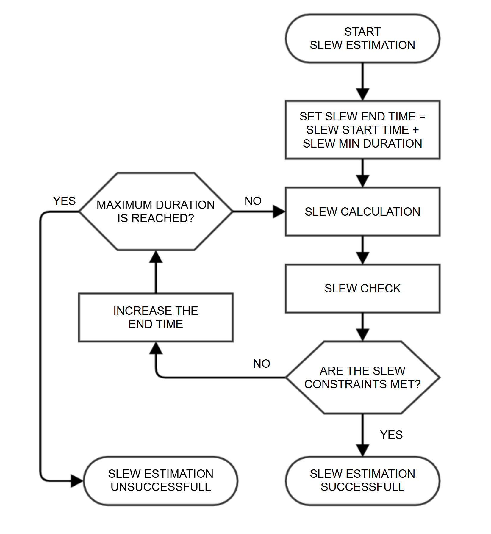
In order to fix the free slew start/end time, depending on the chosen policy, the algorithm follows the next sequence:
Slew duration computation algorithm steps list:
-If the initial slew duration is shorter than the minimum duration allowed an error is provided and the algorithm is interrupted.
If the initial slew duration is longer than the maximum duration allowed, the duration is automatically limited and a warning message is provided.
Then the slew feasibility is checked for the resulting slew time according to the applicable attitude constraints.
If the slew is not feasible an error is provided and the algorithm is interrupted.
An iterative process starts to search for the missing extreme of the slew using the so called binary or half-interval search (that means, dividing the time slot by half every step while a feasible slew can be found until the distance between two consecutive guesses are below certain threshold).
For every step, the slew attitude profile is estimated.
When the new guess provides a feasible slew, a shorter one is tried with limit the minimum duration allowed.
When the new guess doesn’t provide a feasible slew, a longer one is tried.
This iterative search requires a given number of iterations N, function of the given time slot DeltaT and threshold epsilon. In order to estimate performance figures, N is the smallest integer number greater than the following expression: 1 + ln (DeltaT / epsilon) / ln 2.
At the end of the iterative search the estimated duration is extended to add some margins according to the expression DeltaT_Margins = A dot DeltaT + B, where A is the factor to extend it proportionally to the estimated duration and B is the extra fixed amount of time to be added on top.
In case the resulting duration with margins is longer than the initial duration, the duration is automatically limited and a warning message is provided.
Finally the resulting slew duration is returned.
More in detail, this is the pseudo-code describing it’s functionality:
- Validate startBlock time period (shall have end date)
- Validate endBlock time period (shall have start date)

slewStartTime = startBlock.endTime;
slewEndTime = endBlock.startTime;

slewDuration = slewEndTime - slewStartTime

if slewDuration < MIN_SLEW_DURATION:
    reportError ("Invalid initial slew duration guess ... below minimum allowed ...")

if (MAX_SLEW_DURATION > 0.0) && (slewDuration > MAX_SLEW_DURATION):
    reportWarning ("Invalid initial slew duration guess ... above maximum allowed ...")
    reportInfo ("Initial slew duration will be shortened to maximum allowed")

    if slewPolicy == SP_IMMEDIATE:
        reportInfo ("To compute the slew end time before block")
        slewEndTime = slewStartTime + MAX_SLEW_DURATION

    else if slewPolicy == SP_BEFORE_NEXT:
        reportInfo ("To compute the slew start time after block")
        slewStartTime = slewEndTime - MAX_SLEW_DURATION


if slewPolicy == SP_IMMEDIATE:

    - Check that block sliding is allowed

    // Compute minimum slew duration considering all position error cases if any
    // NOTE: At least one is always done when no position error cases are defined which corresponds to zero position error

    slewCase = 0;
    finalEndTime = solutionStartTime;
    validSlew = true;

    do
        - Set current position error case if needed

        validSlewFound = false;
        lastValidTime = slewEndTime;
        lastWrongTime = solutionStartTime + m_slewMinDuration;
        guessEndTime = lastValidTime;
        deltaTime = lastValidTime - lastWrongTime;

        do
            // Use end block reflecting changes on the start and/or end times due to changes on the slew duration
            // (if blocks are allowed to slide then the duration of the block should remain the same)
            if allowBlocksToSlide:
                afterEndTime = guessEndTime + afterDuration

            - Estimate the slew attitude profile            // See "FD Slew Checker" section
            - Check the slew attitude profile => hasBreaks

            // Check for no valid slew solution
            if !validSlewFound && hasBreaks:
                solutionEndTime = guessEndTime
                break

            else:
                validSlewFound = true   // At least one solution already found

                // Check for a new valid solution
                if !hasBreaks:
                    solutionEndTime = guessEndTime
                    lastValidTime = guessEndTime
                else:
                    lastWrongTime = guessEndTime  // last guess invalid


                // Compute next guess
                deltaTime = lastValidTime - lastWrongTime;
                guessEndTime = lastValidTime - deltaTime / 2.0

        while (deltaTime > SE_ACCURACY);

        - Check for invalid slew solution
        - Check for longer slew case duration

        - Continue with next case

    while validSlew && (slewCase < NR_OF_POS_ERR_CASES):

    - Apply margins to the computed slew duration
    - Check that the slew still fits after applying margins


else if slewPolicy == SP_BEFORE_NEXT:

    - Check that block sliding is allowed

    // Compute minimum slew duration considering all position error cases if any
    // NOTE: At least one is always done when no position error cases are defined which corresponds to zero position error
    slewCase = 0
    finalStartTime = solutionEndTime
    validSlew = true

    do
        - Set current position error case if needed

        validSlewFound = false
        lastValidTime = slewStartTime
        lastWrongTime = solutionEndTime - m_slewMinDuration
        guessStartTime = lastValidTime
        deltaTime = lastValidTime - lastWrongTime

        do
            // Use end block reflecting changes on the start and/or end times due to changes on the slew duration
            // (if blocks are allowed to slide then the duration of the block should remain the same)
            if allowBlocksToSlide:
                beforeStartTime = guessStartTime - beforeDuration;

            - Estimate the slew attitude profile   // See "FD Slew Checker" section
            - Check the slew attitude profile

            // Check for no valid slew solution
            if !validSlewFound && hasBreaks:
                solutionStartTime = guessStartTime
                break

            else:
                validSlewFound = true // At least one solution already found

                // Check for a new valid solution
                if !hasBreaks:
                    solutionStartTime = guessStartTime
                    lastValidTime = guessStartTime

                else:
                    lastWrongTime = guessStartTime // last guess invalid

                // Compute next guess
                deltaTime = lastWrongTime - lastValidTime
                guessStartTime = lastValidTime + deltaTime / 2.0

        while (deltaTime > SE_ACCURACY);

        - Check for invalid slew solution
        - Check for longer slew case duration

        - Continue with next case

    while validSlew && (slewCase < NR_OF_POS_ERR_CASES):

    - Apply margins to the computed slew duration
    - Check that the slew still fits after applying margins

- Return slew start and end times, and computed profile
FD Slew Checker
The FD Slew Checker software was delivered by FD as FORTRAN code for the Venus Express and Mars Express mission. It provides several functions to interface it and check the feasibility of a given slew, and one configuration function to hard-code all mission specific configuration parameters.
History:
The FD Slew Checker software was delivered by FD as FORTRAN code for the Venus Express mission. It was not possible to use it directly because this tool only checks the validity of a slew with a fixed time. For planning purpose it is needed a slew estimator instead. As the planning system is developed in C/C++ the code is translated in C to allow the integration into the attitude module called GPTR now deprecated. This library is validated and maintained at the beginning by SIMS and now by PSS.
The first version of the tool has been translated from the FD Slew Checker provided for the mission Venus Express. In order to ease the maintainability of this part of the software, the C translation and the original FORTRAN code have been kept as close as possible to each other.
When Mars Express started using MAPPS the code has been updated with MEX FD Slew Checker code adding the possibility to define a quaternion offset.
For Rosetta the slew estimator has been redesigned to work as standalone library and later included in the AGM module and the FD slew checker tool has been integrated. In addition also the checking algorithms have been redesigned. So from the FD code only the slew calculation is taken. The checking is done outside, in the generated attitude module by the attitude module. This increase the performance and makes it easier to maintain, in fact there is no difference on the checks done in the normal pointing and during the slew estimation. Another improvement was to remove all the hardcoded parameters and make it configurable. So the behaviour can be updated without modifying the source code.
For the Juice spacecraft the slew rotation has been modified in order to keep the sun away from +X instead of –X. Starting from Rosetta the FD Slew Checker tool alone is not distributed anymore. FD only provide a web version of the tool used to validate a pointing timeline and the source code has been opened to SOC for inspection. Since then the FD Slew Checker cannot be kept one to one anymore.
There are only 2 ways to know if there are updates in the code: An e-mail with the changes is sent by FD anytime the web tool software is updated. During software validation comparing the output of the FD web tool with the AGM output.
Slew computation algorithm
The slew algorithm is considering the spacecraft attitude status (orientation + velocity) at the last point of the pointing 1 (previous block end) and the first point of the pointing 2 (current block start):

The slew consists of 3 simultaneous rotations around the following directions:
Sun direction.
Direction perpendicular to the Sun-Yaxis plane.
Direction perpendicular to the previous 2.
The 2 points are fitted with a 2nd degree interpolation. This means that the slew is taking the spacecraft from certain orientation and speed and is accelerating in a such way that the speed is smoothly increased and decreased until matching the end point.
The algorithm accelerates the spacecraft, if possible, with the maximum acceleration allowed and it slows down reducing gradually the acceleration until getting to the maximum speed and 0 m/s2 acceleration. After this point it start slowly increasing the deceleration until reaching the maximum deceleration and the velocity of the destination point.
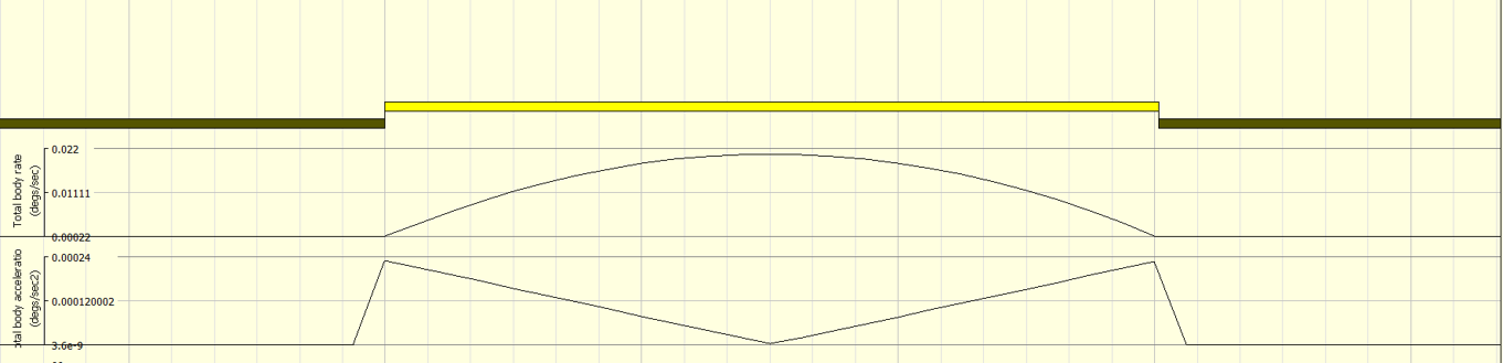
The direction of the 3 rotation as described before allow to keep the Sun away from +X. The spacecraft is slewing in and out of the forbidden zone XY in order to maximize the Sun to +X s/c angle even in the case where the path is not the fastest. If the starting point and end point is power optimized the slew is kept power optimized.
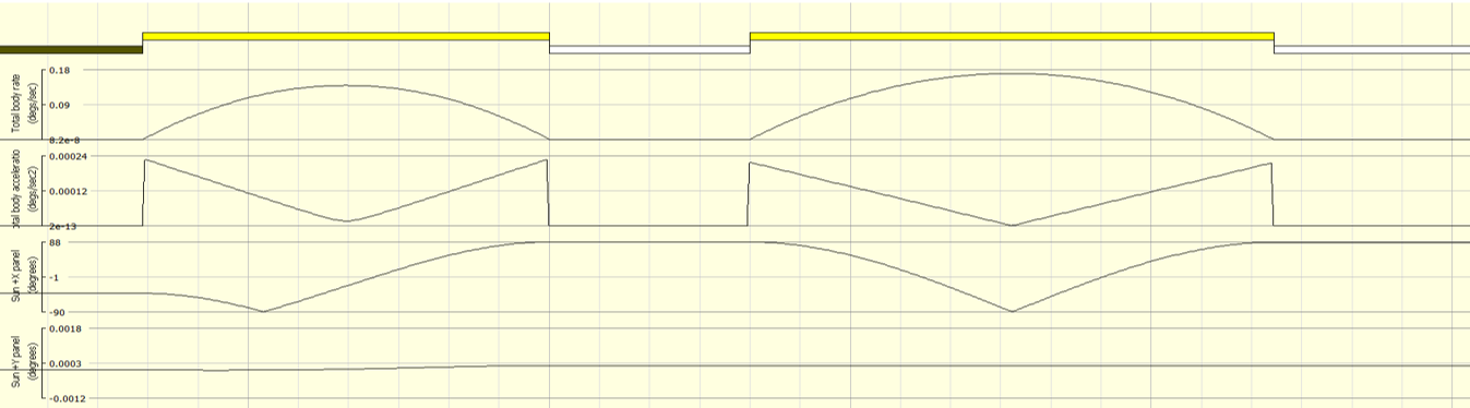
As you can see in the previous picture the slew will always try to minimize the sun on +x.
The slew calculation entry point is:
bool
SlewEstimator::computeSlewFD (
   double slewDuration,
   AGQuat_t slewAttStart,
   AGQuat_t slewAttDerStart,
   AGQuat_t slewAttEnd,
   AGQuat_t slewAttDerEnd,
   AGVec3_t slewScToSunDir,
   AttitudeProfile::AttitudePolyCoef_s &attitudePolyCoef)
Where the inputs are:
slewDuration: Required slew duration in seconds.
slewAttStart: Quaternion with the attitude at the previous block end.
slewAttDerStart: Quaternion derivative with the rates at the previous block end.
slewAttEnd: Quaternion with the attitude at the current block start.
slewAttDerEnd: Quaternion derivative with the rates at the current block start.
slewScToSunDir: Vector with the SC to SUN vector to be considered during the slew calculations.
And returns and attitude profile.
The slew algorithm is taking as input the start state of the spacecraft (quaternion + derivative) and the end state of the spacecraft and it computes the slew in between.
The slew algorithm perform 3 axis rotation based on the following frame:
Xf = - sun pos
Yf = Xf x Zf
Zf = Xf x Yspc
The spacecraft starting/ending position and velocity is then transformed into the new frame. The slew consists of 3 simultaneous rotations. These rotations are defined in terms of the three Euler angles 1-3-2 convention. A smooth 1 segment rotation is applied around Xf, Yf and Zf using a 3rd degree single polynomial function in order to go from the initial state (initial position and velocity) to the final state (final position and velocity). This rotation allow to perform a slew avoiding sun on +X and Y of the spacecraft if the attitude start and ending are not illuminating +X and Y.
It is also possible to perform 3 segment rotation using respectively 2nd, 1st and 2nd degree but this possibility it is not used at the moment.
Configuration
The configuration parameters can be changed at any time and allow the users to define which features to consider for the definition of a feasible slew, which thresholds to use to fix the accuracy of the algorithm and which margins to include in the estimation of the slew duration.
These settings shall be present at the AGM Configuration File.
Main parameters:
The basic parameters for setting the slew are:
SE_SLEWNROFSEG: Code for choosing the number of segments of the slew fitting. This parameter switches between two different implementations:1SEGMENT based on a 1-segment (3rd order) polynomial fit.
3SEGMENT based on a 3-segments (2nd, 1st and 2nd order respectively) polynomial fit.
SE_SLEWPATH: Code for choosing the slew path. This parameter switches between different implementations based either on the sun-line algorithm:sunLineMX: The slew is defined as a rotation around the line to avoid Sun illumination on +X (value not defined in the ESOC FD code).
sunLinePX: The slew is defined as a rotation around the Sun line to avoid Sun illumination on -X (value 1 in the ESOC FD code).
eigenAxis: The slew is defined as a rotation around the eigen-axis line to minimise angular inertia (value 2 in the ESOC FD code).
sunLineXY_MY: Slew around Sun line (-Y)
NORMAL TO X AVOID +Y: Slew around a direction normal to X while avoiding +Y panel illumination.
NORMAL TO X AVOID -Y: Slew around a direction normal to X while avoiding -Y panel illumination.
NORMAL TO X AVOID +Z: Slew around a direction normal to X while avoiding +Z panel illumination.
NORMAL TO X AVOID -Z: Slew around a direction normal to X while avoiding -Z panel illumination.
NORMAL TO Y AVOID +X: Slew around a direction normal to Y while avoiding +X panel illumination.
NORMAL TO Y AVOID -X: Slew around a direction normal to Y while avoiding -X panel illumination.
NORMAL TO Y AVOID +Z: Slew around a direction normal to Y while avoiding +Z panel illumination.
NORMAL TO Y AVOID -Z: Slew around a direction normal to Y while avoiding -Z panel illumination.
NORMAL TO Z AVOID +X: Slew around a direction normal to Z while avoiding +X panel illumination.
NORMAL TO Z AVOID -X: Slew around a direction normal to Z while avoiding -X panel illumination.
NORMAL TO Z AVOID +Y: Slew around a direction normal to Z while avoiding +Y panel illumination.
NORMAL TO Z AVOID -Y: Slew around a direction normal to Z while avoiding -Y panel illumination.
NADIR +X: Slew using nadir pointing with +X axis toward target body.
NADIR -X: Slew using nadir pointing with -X axis toward target body.
NADIR +Y: Slew using nadir pointing with +Y axis toward target body.
NADIR -Y: Slew using nadir pointing with -Y axis toward target body.
NADIR +Z: Slew using nadir pointing with +Z axis toward target body.
NADIR -Z: Slew using nadir pointing with -Z axis toward target body.
CONSTANT ROLL: Slew with a constant roll motion applied during the maneuver.
EIGENAXIS2: Slew around an alternative eigen-axis for inertia minimization.
SE_SUNREFPERCENT: Reference time for Sun direction along the slew duration. Value ranges from 0% at slew start time to 100% at slew end time.SE_DURATIONMIN: Minimum slew duration allowed in seconds. In case the estimated slew is shorter than this value, the final slew duration is made equal to it.SE_DURATIONMAX: Maximum slew duration allowed to shorten estimation. In case the slew to be estimated has an initial guess duration longer than this value, in order to avoid very long computation times, the estimation starts from this maximum. This means that no slew can be longer than this upper limit. No limit will be applied if the parameter is set to 0.SE_ACCURACY: Accuracy for the slew duration estimation in seconds. It is the value used to define when further divisions of the time slot provided for the slew estimation during the binary or half-interval search won’t deliver more accuracy to the result. In particular, it is equivalent to say that the difference between the estimated duration and the shortest feasible duration possible is below this value.SE_MARGINPERCENT: Margin to be applied on the estimated slew duration. This is the percentage value that the estimated duration is extended to increase feasibility beyond the slew checker results. Value ranges from 0% to 100%.SE_MARGINDELTA: Extra time to be added on the estimated slew duration. This is the amount of time that the estimated duration is further extended after being scaled by the percentage provided by SE_MARGINPERCENT.AC_SCANGVELMAX: Maximum angular velocity allowed for the spacecraft in deg/sec.AC_SCANGACCMAX: Maximum angular acceleration allowed for the spacecraft.
Spacecraft Parameters:
These configuration parameters correspond to the characterisation of the spacecraft for performances checking. They can be changed at any time and allow the user to tune the module for a specific mission spacecraft.
SC_INERTIA: Spacecraft inertia tensor. 3x3 Matrix with Kg*2 units.
Reaction Wheels Parameters (Legacy RW model, not for Wheel Momentum Management model):
These configuration parameters correspond to the characterisation of the spacecraft reaction wheels for performances checking. They can be changed at any time and allow the user to tune the module for a specific mission spacecraft.
RW_SC2RW: Spacecraft to reaction wheels orientation matrix. 4x3 Matrix with values between -1.0 and 1.0.This setting is also used by the WMM model.
RW_SCANGMOMMAX: Maximum spacecraft angular momentum to be managed by the reaction wheels in N*m*s.
AC_RWTORQUEMIN: Minimum torque allowed for each reaction wheel in N*m.
AC_RWTORQUEMAX: Maximum torque allowed for each reaction wheel in N*m.
AC_RWEXCURSIONMIN: Minimum wheel excursion allowed for each reaction wheel in N*m*s.
AC_RWEXCURSIONMAX: Maximum wheel excursion allowed for each reaction wheel in N*m*s.
List of Errors:
This appendix is dedicated to list all the different errors handled by the Slew Estimator and their corresponding error messages with some detailed description of their origin and the possible corrective actions to solve them.
Configuration Errors
- Invalid parameter ID for configuration parameter
Origin: SlewEstimator::getParameterInfo().
- Reason: Trying to retrieve the information related to a parameter whose identifier is out of valid range as
defined in the ConfigDefinitions class through the enumerative type ParameterID_e.
Action: Check parameter ID and ensure it is a valid one.
- Invalid parameter ID for configuration parameter
Origin: SlewEstimator::setParameterValue() or SlewEstimator::setParameterValues().
- Reason: Trying to set a parameter whose identifier is out of valid range as defined in the ConfigDefinitions
class through the enumerative type ParameterID_e.
Action: Check parameter ID and ensure it is a valid one.
- Invalid parameter type for configuration parameter
Origin: SlewEstimator::setParameterValue() or SlewEstimator::setParameterValues().
- Reason: Trying to set a parameter whose type is out of valid range as defined in the ConfigDefinitions class
through the enumerative type ParameterType_e.
Action: Check parameter type and ensure it is a valid one.
- Inconsistent information for configuration parameterID, Report conflict with parameter ID to the software support team.
Origin: SlewEstimator::setParameterValue() or SlewEstimator::setParameterValues().
- Reason: Trying to set the parameter ID whose identifier is inconsistent with the expected identifier ID
according to the parameter’s information for the value.
- Action: This error should never occur as it would imply an inconsistency in the parameters information data base itself,
as defined in the ConfigDefinitions class through the variable parameterInfoList[], requiring the modification of the software to correct the inconsistency. Please report it to the software support team to fix the problem if necessary.
- Inconsistent parameter type for configuration parameter ID. Expected parameter type is TYPE instead of TYPE.
Origin: SlewEstimator::setParameterValue() or SlewEstimator::setParameterValues().
- Reason: Trying to set the parameter ID whose expected type TYPE according to the parameter’s information is
inconsistent with the provided type TYPE for the value.
- Action: Check parameter type of the value and ensure it is consistent with the information provided for that
particular parameter.
- Invalid value for configuration parameter ID of type TYPE. Parameter value VAL [UNITS] below lower allowed limit VAL_MIN [UNITS]
Origin: SlewEstimator::setParameterValue() or SlewEstimator::setParameterValues().
- Reason: Trying to set the parameter ID of type TYPE with a number VAL below the minimum number VAL_MIN allowed
for the parameter. Units are provided in the message to allow consistency check.
- Action: Check that all numbers in the parameter value are above the minimum (lower limit) according to the
information provided for that particular parameter. Keep in mind that for some types it could be the integer limit that applies apply while for some others it could be the real one. Due to this both lower limits shall be checked to verify whether they are defined or not for the given parameter.
- Invalid value for configuration parameter ID of type TYPE. Parameter value VAL [UNITS] above upper allowed limit VAL_MAX [UNITS]
Origin: SlewEstimator::setParameterValue() or SlewEstimator::setParameterValues().
- Reason: Trying to set the parameter ID of type TYPE with a number VAL above the maximum number VAL_MAX allowed
for the parameter. Units are provided in the message to allow consistency check.
- Action: Check that all numbers in the parameter value are below the maximum (upper limit) according to the
information provided for that particular parameter. Keep in mind that for some types it could be the integer limit that applies apply while for some others it could be the real one. Due to this both lower limits shall be checked to verify whether they are defined or not for the given parameter.
- Invalid value for configuration parameter ID of type PT_SLEWFIT. The only valid values are 1SEGMENT and 3SEGMENT.
Origin: SlewEstimator::setParameterValue() or SlewEstimator::setParameterValues().
Reason: Trying to set a parameter ID of type PT_SLEWFIT with an invalid value.
Action: Check that the provided value is one of the valid/supported ones as described in the error message.
- Invalid value for configuration parameter ID of type PT_SLEWPATH. The only valid values are SUN_LINE_MX, SUN_LINE_PX and EIGEN_AXIS.
Origin: SlewEstimator::setParameterValue() or SlewEstimator::setParameterValues().
Reason: Trying to set a parameter ID of type PT_SLEWPATH with an invalid value.
Action: Check that the provided value is one of the valid/supported ones as described in the error message.
Slew Estimation Errors
The following errors can occur during the execution of the specific features of the software. They could be due to errors in different modules of the software but the SlewEstimator class handles them in a generic way for reporting.
- Invalid configuration due to undefined parameter ID
Origin: SlewEstimator::checkSlew() or SlewEstimator::estimateSlew().
- Reason: Trying to check or estimate a slew with an invalid configuration. In particular, the configuration
parameter whose identifier is ID is not defined or has been set to an invalid value. This message is always shown when the slew estimation component is used before configuring it. Do not forget that no default values are defined and all parameters must be configured properly before using the software. It is also possible that, during any configuration action, one of the parameters is set to a value out of limits marking the parameter as undefined (invalid) until properly configured.
Action: Configure the offending parameter properly.
- Invalid slew time range VAL [UNITS] below minimum slew duration allowed VAL_MIN [UNITS]
Origin: SlewEstimator::checkSlew() or SlewEstimator::estimateSlew().
- Reason: Trying to check or estimate a slew for a slew time slot VAL below the minimum allowed duration for a
slew VAL_MIN as defined by the parameter PID_SE_DURATIONMIN. Units are provided in the message to allow consistency check.
- Action: Check that the slew time slot given for the slew check/estimation is indeed the desired one instead
of a longer one that avoids the conflict. If it is not, correct it to comply with the minimum slew duration allowed constraint, otherwise change the configuration parameter provided above accordingly to allow shorter durations.
- Invalid non-defined attitude profile at the start of the slew.
Origin: SlewEstimator::checkSlew() or SlewEstimator::estimateSlew().
- Reason: Trying to check or estimate a slew with a non-defined (invalid) attitude profile before the slew slot.
This could be due to empty non-defined attitude profiles or attitude profiles that, during the definition, went through errors or inconsistencies that mark them as non-defined (invalid).
- Action: Verify that the profile was defined with valid information (consistent start and end times,
valid single values or tables…) or inspect the profiles to identify the possible cause of the problem to correct it. In any case the profile must be properly set before using it again. It is a good practice to check for profile’s definition status after creation or modification using their public interfaces.
- Invalid non-defined attitude profile at the end of the slew.
Origin: SlewEstimator::checkSlew() or SlewEstimator::estimateSlew().
- Reason: Trying to check or estimate a slew with an non-defined (invalid) Sun direction profile during the slew slot.
This could be due to empty non-defined direction profiles or direction profiles that, during the definition, went through errors or inconsistencies that mark them as non-defined (invalid).
- Action: Verify that the profile was defined with valid information (consistent start and end times, valid single
values or tables…) or inspect the profiles to identify the possible cause of the problem to correct it. In any case the profile must be properly set before using it again. It is a good practice to check for profile’s definition status after creation or modification using their public interfaces.
- Invalid attitude profile at the start of an IMMEDIATE slew. Attitude profile must be defined at the start of the slew slot.
Origin: SlewEstimator::estimateSlew() for slew policy IMMEDIATE.
- Reason: Trying to check or estimate an IMMEDIATE slew, the attitude profile before the slew is not defined for
a time period that includes the start time of the slew slot. In particular, it either starts later or ends earlier than the start of the slew slot.
- Action: Correct or extend the time definition period for the profile to ensure that the start time of the slew
slot is covered by the profile.
- Invalid attitude profile at the end of an IMMEDIATE slew. Attitude profile must cover the whole time range of the slew slot.
Origin: SlewEstimator::estimateSlew() for slew policy IMMEDIATE.
- Reason: Trying to check or estimate an IMMEDIATE slew, the attitude profile after the slew is not defined for
the whole time slot required to estimate the slew due to the nature of the iterative search of the end time. In particular, it either starts later than the start of the time slot or ends earlier than the end of the time slot.
Action: Correct or extend the time definition period for the profile to ensure that the whole time slot is covered by the profile.
- Invalid Sun direction profile for an IMMEDIATE slew. Sun direction profile must cover the whole time range of the slew slot.
Origin: SlewEstimator::estimateSlew() for slew policy IMMEDIATE.
- Reason: Trying to check or estimate an IMMEDIATE slew, the Sun direction profile is not defined for the whole
time range required to estimate the slew due to the nature of the iterative search of the end time (and consequently the reference point for the Sun direction). In particular, it either starts later than the start of the time slot or ends earlier than the end of the time slot.
Action: Correct or extend the time definition period for the profile to ensure that the whole time slot is covered by the profile.
- Invalid attitude profile at the start of a BEFORE_NEXT slew. Attitude profile must be defined at the start of the slew slot.
Origin: SlewEstimator::estimateSlew() for slew policy BEFORE_NEXT.
- Reason: Trying to check or estimate a BEFORE_NEXT slew, the attitude profile before the slew is not defined for
the whole time period required to estimate the slew due to the nature of the iterative search of the start time. In particular, it either starts later than the start of the time slot or ends earlier than the end of the time slot.
Action: Correct or extend the time definition period for the profile to ensure that the whole time slot is covered by the profile.
- Invalid attitude profile at the end of a BEFORE_NEXT slew. Attitude profile must be defined at the end of the slew slot.
Origin: SlewEstimator::estimateSlew() for slew policy BEFORE_NEXT.
- Reason: Trying to check or estimate a BEFORE_NEXT slew, the attitude profile after the slew is not defined for
a time period that includes the end time of the slew slot. In particular, it either starts later or ends earlier than the end of the slew slot.
- Action: Correct or extend the time definition period for the profile to ensure that the end time of the slew slot
is covered by the profile.
- Invalid Sun direction profile for a BEFORE_NEXT slew. Sun direction profile must cover the whole time range of the slew slot.
Origin: SlewEstimator::estimateSlew() for slew policy BEFORE_NEXT.
- Reason: Trying to check or estimate a BEFORE_NEXT slew, the Sun direction profile is not defined for the whole time
period required to estimate the slew due to the nature of the iterative search of the start time (and consequently the reference point for the Sun direction). In particular, it either starts later than the start of the time slot or ends earlier than the end of the time slot.
Action: Correct or extend the time definition period for the profile to ensure that the whole time slot is covered by the profile.
- Error during execution of the ESOC FD slew checker. Invalid attitude or attitude derivative when converting into quaternions.
Origin: SlewEstimator::checkSlew() or SlewEstimator::estimateSlew().
Reason: Error converting the input attitude or attitude derivative matrices into quaternions in the FD Slew Checker code.
- Action: As no additional information is delivered by the FD Slew Checker, the only action possible is to verify the input
attitude profiles for invalid or singular values. Please report it to the software support team to help fixing the problem if possible.
- Error during execution of the ESOC FD slew checker. Reason unknown (slew time calculation or slew check aborted).
Origin: SlewEstimator::checkSlew() or SlewEstimator::estimateSlew().
Reason: Unknown problem during the execution of the slew time calculation or slew check routines in the FD Slew Checker.
- Action: As no additional information is delivered by the FD Slew Checker no corrective action is possible.
Please report it to the software support team to help fixing the problem if possible.
- Error during execution of the ESOC FD slew checker. Reason unknown (error flag out of known range).
Origin: SlewEstimator::checkSlew() or SlewEstimator::estimateSlew().
Reason: Unknown error flag returned by the FD Slew Checker.
- Action: This error should never occur as all the expected error flags are properly handled by the software.
Otherwise, it would imply that the FD Slew Checker is returning unexpected error flags. Please report it to the software support team to fix the problem if necessary.
- Impossible to find a feasible slew for the given time range.
Origin: SlewEstimator::estimateSlew() for slew policy IMMEDIATE.
Reason: Trying to estimate a slew for a time slot that is not long enough to comply with the requested constraints.
- Action: The problem should get solved by extending the time slot provided to find the feasible slew but in some
special cases the attitude or Sun direction profiles for the specific slew might impose certain conditions that make the slew unfeasible no matter how long the time slot provided is. In case extending the time doesn’t solve the problem analyse the initial and final conditions, together with the Sun direction to ensure that basic constraints are not violated by them.
- Impossible to find a feasible slew (due to margins) for the given time range.
Origin: SlewEstimator::estimateSlew() for slew policy IMMEDIATE.
- Reason: Trying to estimate a slew that is feasible for the given time slot, it is not possible to check after
the margins, as defined by parameters SE_MARGINPERCENT and SE_MARGINDELTA, are added. This is typically due to the fact that the estimated start or end time for the slew after applying margins falls out of the given time slot, being then in principle impossible to evaluate the profiles.
- Action: Extend the time slot for the estimation and provide the profiles defined accordingly for the new time slot.
The safest choice would be to extend the original time slot using the same percentage an delta times provided by the configuration parameters provided above.
- Invalid or not supported slew policy.
Origin: SlewEstimator::estimateSlew().
- Reason: Trying to estimate a slew with and invalid slew policy as defined in the SlewEstimator class through the
enumerative type SlewPolicy_e.
Action: Check the slew policy and ensure it is a valid/supported one.
- Invalid slew profile due to slew constraint(s) breaking.
S/C rate check broken for CONF configuration and SLEW path.
S/C angular acceleration check broken for CONF configuration and SLEW path.
RW angular momentum check broken for CONF configuration and SLEW path.
RW torque check broken for CONF configuration and SLEW path.
Origin: SlewEstimator::checkSlew() or SlewEstimator::estimateSlew().
- Reason: Trying to check or estimate a slew, the constraints breaks listed in the error message occur for the best estimation.
In general, all four (S/C rate, S/C angular acceleration, RW angular momentum and RW torque) could happen at the same time for a given slew but more often only some of them will do. In that case, the labels CONF and SLEW indicate which configuration (USER for user defined or WORST for worst case) and which slew path (SHORT for the shorter and LONG for the longer) are the ones violating the constraint breaks for each specific break.
- Action: In most of the cases extending the time slot for the slew estimation is enough to solve the problem.
Nevertheless, if the duration should be long enough to cope with the constraints, the configuration parameters could be reviewed to identify possible errors in the maximum allowed values for those indicators or other spacecraft specifications. Additionally, in case the error is for a configuration or slew path that shouldn’t be considered, the corresponding checks should be disabled.
Wheel Momentum Management
The Wheel Momentum Management module of AGM is in charge of computing the wheel momentum and torques resulting from following the given pointing profile, which can be checked against the reaction wheel momentum and torque limits defined in the AGM configuration file. See “Reaction Wheels and Wheel Momentum Management” sub-section in the “AGM Configuration File” section of this file 60_agm:Reaction Wheels and Wheel Momentum Management.
AGM could be configured to use a 3-wheel or 4-wheel configuration cases.
AGM computes the following quantities or profiles related to the wheel momentum management:
Gravity Gradient Torques (GGT): The X, Y, Z components of the gravity gradient torque due to the target body in Nm.
Body rates: The X, Y, Z components of the spacecraft body rates in radians/second.
Reaction Wheel Assembly Momentum: The X, Y, Z component of the reaction wheel assembly momentum in Nms.
Reaction Wheels Momentum: The momentum of each reaction wheel 1, 2, 3, 4 in Nms.
Reaction Wheels Torque: The torque of each reaction wheel 1, 2, 3, 4 in Nm.
All these values could be requested to AGM through OSVE while using datapack overlays. See “Wheel Momentum Management” in the Wheel Momentum Management section.
IMPORTANT NOTE: OSVE doesn’t support Wheel Momentum Management Events as MAPPS does for the time being.
NOTE: See AGM Multi-body Approach in order to properly configure the AGM object’s gravities and their hierarchy.
Wheel accumulated momentum reset during Wheels Off Loading (WOLs)
AGM is able to reset or set the reaction wheels accumulated momentum during the WOL block. With this we aim to simulate as close as possible how the reaction wheels are handled during the actual WOLs in order to accommodate their momentum’s to reasonable value in order to proceed with the next pointing blocks.
In order to do so the user shall update the AGM predefined WOL block in order to allow wheel momentum resets:
The attribute “resetWheelMomentum” shall be added to the “planning” element it can have 2 states: “true” and “false”, this attribute shall be optional with default value “false” to support legacy behaviour, see the following example:
<block name="MWOL" ref="OBS">
 <metadata>
 <comment>MWOL</comment>
 <planning resetWheelMomentum="true" isMaintenance="true" hasInternalSlews="true" allowAttitude="false" allowHgaRequest="false">
 <intSlewDurationBefore units="min">10</intSlewDurationBefore>
 <intSlewDurationAfter units="min">10</intSlewDurationAfter>
 </planning>
 </metadata>
 <attitude ref="track">
   <boresight ref="SC_Zaxis" />
   <target ref="Europa" />
   <phaseAngle ref="powerOptimised">
     <yDir> false </yDir>
   </phaseAngle>
 </attitude>
</block>
If the “resetWheelMomentum” attribute is set to “true” and the AGM configuration is set to work with 3 reaction wheels, then user can define in the relative XML PTR block the sub node: “wheel” inside the new element “wheelMomentumTarget”, inside the existing element “metadata”.
Example:
<block ref="MWOL">
 <metadata>
   <wheelMomentumTarget>
     <wheel number="1" unit="Nms">2</wheel>
     <wheel number="2" unit="Nms">2</wheel>
     <wheel number="3" unit="Nms">2</wheel>
   </wheelMomentumTarget>
 </metadata>
 <startTime> 2030-06-29T09:15:00 </startTime>
 <endTime> 2030-06-29T09:32:51 </endTime>
</block>
The “number” attribute is mandatory and shall be always in range 1 to 4. The “unit” attribute is mandatory and shall be always set to “Nms” this is to force the user to be aware of the unit used. The wheel momentum value shall be a sign float number within the allowed range (AC_RW_WMM_MOMENTUMMIN, AC_RW_WMM_MOMENTUMMAX) set in the AGM Configuration file.
If one of the wheel momentum value is not specified, this wheel remain in the same state as it is at the moment of inserting the maintenance WOL block.
If the value is defined and valid the wheelMomentum of each wheel will be set to the value specified by the user, and the wheelAssembly updated accordingly, for the entire duration of the maintenance block (from startTime+intSlewDurationBefore to endTime-intSlewDurationAfter).
if the “resetWheelMomentum” attribute is set to “true” and the AGM configuration is set to work with 4 reaction wheels, the user will be allowed to define in the relative XML PTR block with only a “wheelAssembly” node inside the node “wheelMomentumTarget”, inside the existing “metadata” node.
Example:
<block ref="MWOL">
 <metadata>
   <wheelMomentumTarget>
     <wheelAssembly unit="Nms">
       <x> 10 </x>
       <y> 15 </y>
       <z> 20 </z>
     </wheelAssembly>
   </wheelMomentumTarget>
 </metadata>
 <startTime> 2030-06-29T09:15:00 </startTime>
 <endTime> 2030-06-29T09:32:51 </endTime>
</block>
The “unit: is mandatory and shall be always set to “Nms” this is to force the user to be aware of the unit used. The wheel momentum vector coordinates values shall be a sign float number within AC_RW_WMM_MAXASSMOMENTUM absolute range.
If the assembly wheel momentum reset is present, the wheelMomentum assembly will be set to the value specified by the user, for the entire duration of the maintenance block, so from “startTime + (borderSlewDurationBefore + intSlewDurationBefore)” to “endTime - (intSlewDurationAfter + borderSlewDurationAfter)”.
References:
PSS-SDG-0001: https://s2e2.cosmos.esa.int/confluence/pages/viewpage.action?spaceKey=PSS&title=PSS-SDG-0001
JUICE Science Profiles Feasibility Checks, JUICE_ScienceProfilesFeasibility.pdf Issue 01, 04-06-2018
Assumptions for JUICE AOCS / Navigation Analyses, JUI-ADST-SYS-TN-000463 Issue 02, 01-03-2021
[AGM] Document AGM Slew and RW computations: https://s2e2.cosmos.esa.int/jira/browse/SC6-246
Wheel accumulated momentum reset during Wheel Off Loading: https://s2e2.cosmos.esa.int/jira/browse/PSSPCR-751
PSSPCR-751 testing failure: wheel momenta not reset as expected in a WoL block: https://s2e2.cosmos.esa.int/jira/browse/PSSPCR-1302
Report of Test PSSPCR-751: Wheel accumulated momentum reset during Wheel Off Loading: https://s2e2.cosmos.esa.int/confluence/display/SOCDEV/Report+of+Test+PSSPCR-751%3A+Wheel+accumulated+momentum+reset+during+Wheel+Off+Loading
Wheel Momentum Management: https://s2e2.cosmos.esa.int/confluence/display/PSS/Wheel+Momentum+Management
MAPPS Wheel Momentum Events: https://s2e2.cosmos.esa.int/confluence/display/PSS/MAPPS+Wheel+Momentum+Events